HFCT5201B Avago Technologies US Inc., HFCT5201B Datasheet
HFCT5201B
Specifications of HFCT5201B


Related parts for HFCT5201B


HFCT5201B Summary of contents
Page 1
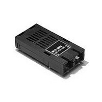
HFCT-5201 155 Mb/s Single Mode Fiber Transceiver for ATM, SONET OC-3/SDH STM-1 Part of the Avago METRAK family Data Sheet Description General The HFCT‑5201 is a 1300 nm laser based transceiver. It provides a very cost‑effective solution for medium haul ...
Page 2
ELECTRICAL S UBAS S EMBLY DATA DATA AMP LIFIER IC S IGNAL DETECT DATA LAS ER DRIVER DATA IC P OWER LAS ER BIAS MONITOR Figure 1. Block Diagram Receiver Signal Detect As the input optical power ...
Page 3
LINEAR EXTRAP OLATION THROUGH 10 -7 DATA ACTUAL 10 -4 DATA -10 10 -11 10 -12 10 -13 10 -14 10 ...
Page 4
V difference in supply levels. Also, noise immunity may be compromised for the HFCT‑5201 trans‑ ceiver because the ground plane is now the V point. The suggested power supply filter circuit shown in Figure 4, Recommended ...
Page 5
+0.25 0.46 3.12 -0. Ø (0.123) 0.018 +0.010 -0.002 ° ° + ° ° ° ° ° ° 20.32 ° ° (0. 2.54 ° ° (0.1) ° ° + ° ° ° ° 2.54 (0.1) 33.02 ...
Page 6
Performance Specifications Absolute Maximum Ratings Stresses in excess of the absolute maximum ratings can cause catastrophic damage to the device. Limits apply to each parame‑ ter in isolation, all other parameters having values within the recommended operating conditions. It should ...
Page 7
Table 2. Pin Out Table Pin Symbol Functional Description Mounting Studs The mounting studs are provided for transceiver mechanical attachment to the circuit board. They are embedded in the non‑conductive plastic housing and are not connected to the transceiver internal ...
Page 8
Ordering Information Temperature Range 0°C to +70°C HFCT‑5201B Black Case HFCT‑5201D Blue Case Temperature Range -40°C to +85°C HFCT‑5201A Black Case HFCT‑5201C Blue Case Supporting Documentation Application Note 1098 Characterization Report Interim Reliability Data Sheet 8 ...