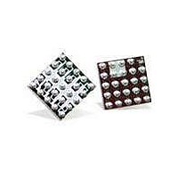
IP4041CX25/LF/P,13 NXP Semiconductors, IP4041CX25/LF/P,13 Datasheet - Page 5

IP4041CX25/LF/P,13
Manufacturer Part Number
IP4041CX25/LF/P,13
Description
IC FILTER/ESD PROT 10CH WLCSP25
Manufacturer
NXP Semiconductors
Datasheet
1.IP4041CX25LFP13.pdf
(12 pages)
Specifications of IP4041CX25/LF/P,13
Termination Style
Surface Mount (SMD,SMT)
Filter Type
Signal Line
Voltage - Rated
5.5V
Mounting Type
Surface Mount
Operating Voltage
- 0.5 V to 5.5 V
Channels
10 Channels
Breakdown Voltage
6 V to 15 V
Capacitance
50 pF
Package / Case
WLCSP-25
Power Dissipation Pd
500 mW
Operating Temperature Range
- 35 C to + 85 C
Lead Free Status / RoHS Status
Lead free / RoHS Compliant
Inductance
-
Lead Free Status / Rohs Status
Lead free / RoHS Compliant
Other names
568-5067-2
934061469135
934061469135
NXP Semiconductors
7. Application information
IP4041CX25_1
Product data sheet
7.1 Insertion loss
The insertion loss measurement configuration of a typical 50 Ω NetWork Analyzer (NWA)
system for evaluation of the IP4041CX25 is shown in
The insertion loss of all channels for frequencies up to 6 GHz is displayed in
Fig 3.
Fig 4.
(10) Channel 1 (pins A1 and E1).
(1) Channel 10 (pins B5 and D5).
(2) Channel 9 (pins B4 and D4).
(3) Channel 8 (pins B3 and D3).
(4) Channel 7 (pins B2 and D2).
(5) Channel 6 (pins B1 and D1).
(6) Channel 5 (pins A5 and E5).
(7) Channel 4 (pins A4 and E4).
(8) Channel 3 (pins A3 and E3).
(9) Channel 2 (pins A2 and E2).
(dB)
s
21
Frequency response measurement configuration
10
20
30
40
50
Measured insertion loss magnitudes
0
1
All information provided in this document is subject to legal disclaimers.
Rev. 01 — 12 February 2010
10-channel integrated filter network with ESD input protection
10
50
V gen
IN
measurement
on-device
DUT
10
2
OUT
008aaa203
Figure
50
10
3.
3
(10)
(6)
(7)
(8)
(9)
IP4041CX25
f (MHz)
001aak682
© NXP B.V. 2010. All rights reserved.
(1)
(2)
(3)
(4)
(5)
10
Figure
4
4.
5 of 12


