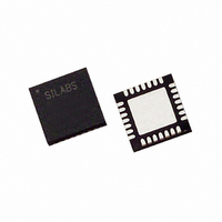
CP2102-GMR Silicon Laboratories Inc, CP2102-GMR Datasheet - Page 5

CP2102-GMR
Manufacturer Part Number
CP2102-GMR
Description
USB to UART Bridge 28-Pin QFN T/R
Manufacturer
Silicon Laboratories Inc
Specifications of CP2102-GMR
Package
28QFN
Operating Temperature
-40 to 85 °C
Applications
USB
Interface
UART
Voltage - Supply
3 V ~ 3.6 V
Package / Case
28-VQFN Exposed Pad, 28-HVQFN, 28-SQFN, 28-DHVQFN
Mounting Type
Surface Mount
Maximum Operating Temperature
+ 125 C
Minimum Operating Temperature
- 55 C
Mounting Style
SMD/SMT
Operating Supply Voltage
3.6 V
Supply Current (max)
100 mA
Lead Free Status / RoHS Status
Lead free / RoHS Compliant
For Use With
336-1161 - KIT EVALUATION FOR CP2102
Lead Free Status / Rohs Status
Details
Other names
336-1802-2
CP2102-GMR
Q4435029
CP2102-GMR
Q4435029
Available stocks
Company
Part Number
Manufacturer
Quantity
Price
Company:
Part Number:
CP2102-GMR
Manufacturer:
MAXIM
Quantity:
2 300
Company:
Part Number:
CP2102-GMR
Manufacturer:
SiliconL
Quantity:
12 000
Company:
Part Number:
CP2102-GMR
Manufacturer:
SIGNALS
Quantity:
5
Part Number:
CP2102-GMR
Manufacturer:
SILICON LABS/芯科
Quantity:
20 000
Company:
Part Number:
CP2102-GMR.
Manufacturer:
SILICON
Quantity:
15 000
2. Electrical Specifications
Table 2. Global DC Electrical Characteristics
V
Table 3. UART and Suspend I/O DC Electrical Characteristics
V
Table 1. Absolute Maximum Ratings
Parameter
Supply Voltage
Supply Current
Supply Current
Supply Current - USB Pull-up
Specified Operating Temperature Range
Notes:
Parameters
Output High Voltage
Output Low Voltage
Input High Voltage
Input Low Voltage
Input Leakage Current
Parameter
Ambient Temperature under Bias
Storage Temperature
Voltage on any I/O Pin or RST with respect to GND
Voltage on V
Maximum Total Current through V
Maximum Output Current sunk by RST or any I/O pin
Note: Stresses above those listed may cause permanent device damage. This is a stress rating only, and functional
DD
DD
1. USB Pull-up Current should be added for total supply current.
2. The USB Pull-up supply current values are calculated values based on USB specifications.
= 3.0 to 3.6 V, –40 to +85 °C unless otherwise specified
= 3.0 to 3.6 V, –40 to +85 °C unless otherwise specified
operation of the devices at or exceeding the conditions in the operation listings of this specification is not implied.
Exposure to maximum rating conditions for extended periods may affect device reliability.
DD
1
1
with respect to GND
2
DD
and GND
I
I
I
I
OH
I
Conditions
OH
OL
I
OH
OL
OL
= –10 mA
= 8.5 mA
= –10 µA
= 25 mA
= –3 mA
= 10 µA
Normal Operation;
Rev. 1.4
V
V
Suspended:
Conditions
REG
REG
Conditions
Enabled
Enabled
V
V
DD
DD
Min
2.0
—
—
—
—
—
—
– 0.7
– 0.1
–0.3
–0.3
Min
–55
–65
Min
–40
3.0
—
—
—
—
—
V
DD
Typ
1.0
25
—
—
—
—
—
—
– 0.8
Typ
Typ
200
—
—
—
—
—
—
3.3
20
80
—
Max
0.6
0.1
0.8
50
Max
—
—
—
—
—
125
150
500
100
Max
5.8
4.2
100
228
+85
3.6
26
CP2102
UNITS
Units
Units
mA
mA
mA
°C
°C
µA
µA
µA
°C
V
V
V
V
V
V
V
5


