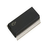
CY7C68000-56PVC Cypress Semiconductor Corp, CY7C68000-56PVC Datasheet - Page 5

CY7C68000-56PVC
Manufacturer Part Number
CY7C68000-56PVC
Description
Manufacturer
Cypress Semiconductor Corp
Datasheet
1.CY7C68000-56PVC.pdf
(14 pages)
Specifications of CY7C68000-56PVC
Number Of Transceivers
1
Power Supply Requirement
Single
Operating Supply Voltage (typ)
3.3V
Operating Temperature Classification
Commercial
Operating Supply Voltage (max)
3.6V
Operating Supply Voltage (min)
3V
Dual Supply Voltage (typ)
Not RequiredV
Dual Supply Voltage (max)
Not RequiredV
Dual Supply Voltage (min)
Not RequiredV
Mounting
Surface Mount
Operating Temperature (max)
70C
Operating Temperature (min)
0C
Lead Free Status / RoHS Status
Not Compliant
Available stocks
Company
Part Number
Manufacturer
Quantity
Price
Company:
Part Number:
CY7C68000-56PVC
Manufacturer:
INFINEON
Quantity:
67
Company:
Part Number:
CY7C68000-56PVC
Manufacturer:
CY
Quantity:
129
Company:
Part Number:
CY7C68000-56PVCT
Manufacturer:
EPCOS
Quantity:
4 000
Document #: 38-08016 Rev. *H
Table 5-1. Pin Descriptions (continued)
SSOP QFN
56
55
53
51
50
48
46
45
44
43
41
40
38
36
34
33
10
19
20
26
25
1
9
49
48
46
44
43
41
39
38
37
36
34
33
31
29
27
26
50
12
13
19
18
3
2
D0
D1
D2
D3
D4
D5
D6
D7
D8
D9
D10
D11
D12
D13
D14
D15
CLK
Reset
XcvrSelect
TermSelect
Suspend
LineState1
LineState0
Name
Output
Output
Output
Type
Input
Input
Input
Input
I/O
I/O
I/O
I/O
I/O
I/O
I/O
I/O
I/O
I/O
I/O
I/O
I/O
I/O
I/O
I/O
Default
[1]
N/A
N/A
N/A
N/A
Bidirectional Data Bus. This bidirectional bus is used as the entire data
bus in the 8-bit bidirectional mode or the least significant eight bits in the 16-
bit mode or under the 8-bit unidirectional mode these bits are used as inputs
for data, selected by the RxValid signal.
Bidirectional Data Bus. This bidirectional bus is used as the upper eight
bits of the data bus when in the 16-bit mode, and not used when in the 8-bit
bidirectional mode. Under the 8-bit unidirectional mode these bits are used
as outputs for data, selected by the TxValid signal.
Clock. This output is used for clocking the receive and transmit parallel data
on the D[15:0] bus.
Active HIGH Reset. Resets the entire chip. This pin can be tied to V
through a 0.1 μF capacitor and to GND through a 100 K resistor for a 10
msec RC time constant.
Transceiver Select. This signal selects between the Full Speed (FS) and
the High Speed (HS) transceivers:
0: HS transceiver enabled
1: FS transceiver enabled
Termination Select. This signal selects between the between the Full
Speed (FS) and the High Speed (HS) terminations:
0: HS termination
1: FS termination
Suspend. Places the CY7C68000 in a mode that draws minimal power from
supplies. Shuts down all blocks not necessary for Suspend/Resume opera-
tions. While suspended, TermSelect must always be in FS mode to ensure
that the 1.5 K ohm pull-up on DPLUS remains powered.
0: CY7C68000 circuitry drawing suspend current
1: CY7C68000 circuitry drawing normal current
Line State. These signals reflect the current state of the single-ended
receivers. They are combinatorial until a “usable” CLK is available then they
are synchronized to CLK. They directly reflect the current state of the
DPLUS (LineState0) and DMINUS (LineState1).
D– D+ Description
0 0 0: SE0
0 1 1: ‘J’ State
1 0 2: ‘K’ State
1 1 3: SE1
Line State. These signals reflect the current state of the single-ended
receivers. They are combinatorial until a ‘usable’ CLK is available then they
are synchronized to CLK. They directly reflect the current state of the
DPLUS (LineState0) and DMINUS (LineState1).
D– D+ Description
00–0: SE0
01–1: ‘J’ State
10–2: ‘K’ State
11–3: SE1.
Description
CY7C68000
Page 5 of 14
CC


