SY89833ALMG Micrel Inc, SY89833ALMG Datasheet - Page 3
SY89833ALMG
Manufacturer Part Number
SY89833ALMG
Description
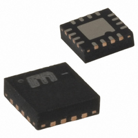
3.3V 1:4 PECL Fanout Buffer
Manufacturer
Micrel Inc
Series
Precision Edge®r
Type
Fanout Buffer (Distribution), Translatorr
Datasheet
1.SY89833ALMG.pdf
(12 pages)
Specifications of SY89833ALMG
Number Of Circuits
1
Ratio - Input:output
1:4
Differential - Input:output
Yes/Yes
Input
CML, LVDS, LVPECL
Output
LVDS
Frequency - Max
2GHz
Voltage - Supply
3 V ~ 3.6 V
Operating Temperature
-40°C ~ 85°C
Mounting Type
Surface Mount
Package / Case
16-MLF®, QFN
Frequency-max
2GHz
Number Of Outputs
8
Operating Supply Voltage (max)
3.6V
Operating Temp Range
-40C to 85C
Propagation Delay Time
0.47ns
Operating Supply Voltage (min)
3V
Mounting
Surface Mount
Pin Count
16
Operating Supply Voltage (typ)
3.3V
Package Type
MLF EP
Quiescent Current
100mA
Duty Cycle
53%
Operating Temperature Classification
Industrial
Lead Free Status / RoHS Status
Lead free / RoHS Compliant
Other names
576-3501-5
Available stocks
Company
Part Number
Manufacturer
Quantity
Price
Company:

Part Number:
SY89833ALMG
Manufacturer:
IDT
Quantity:
60


Micrel, Inc.
Pin Description
March 2009
Pin Number
15, 16
9, 12
7, 14
1, 2
3, 4
5, 6
10
11
13
8
Pin Name
VREF-AC
Q0, /Q0
Q1, /Q1
Q2, /Q2
Q3, /Q3
/IN, IN
GND
VCC
EN
VT
Pin Function
LVDS Differential Outputs: Normally terminated with 100Ω across the pair (Q,
/Q). See “LVDS Outputs” section, Figure 2a. Unused outputs should be
terminated with a 100Ω resistor across each pair.
This single-ended TTL/CMOS-compatible input functions as a synchronous
output enable. The synchronous enable ensures that enable/disable will only
occur when the outputs are in a logic LOW state. Note that this input is internally
connected to a 25kΩ pull-up resistor and will default to logic HIGH state
(enabled) if left open.
Differential Input: This input pair is the differential signal input to the device.
Input accepts AC- or DC-Coupled differential signals as small as 100mV. Each
pin of the pair internally terminates to a VT pin through 50Ω. Note that this input
will default to an intermediate state if left open. Please refer to the “Input
Interface Applications” section for more details.
Reference Voltage: This output biases to V
Coupling the input (IN, /IN). For AC-Coupled applications, connect VREF-AC to
VT pin and bypass with 0.1µF low ESR capacitor to V
Applications” section for more details. Maximum sink/source current is ±1.5mA.
Due to the limited drive capability, each VREF-AC pin is only intended to drive its
respective VT pin.
Input Termination Center-Tap: Each side of the differential input pair terminates
to the VT pin. The VT pin provides a center-tap to a termination network for
maximum interface flexibility. See “Input Interface Applications” section for more
details.
Ground. GND pin and exposed pad must be connected to the most negative
potential of the device ground.
Positive Power Supply: Bypass with 0.1µF//0.01µF low ESR capacitors and
place as close to each VCC pin as possible.
3
CC
–1.4V. It is used when AC-
hbwhelp@micrel.com
CC
. See “Input Interface
or (408) 955-1690
M9999-032609-A
SY89833AL
Related parts for SY89833ALMG
Image
Part Number
Description
Manufacturer
Datasheet
Request
R

Part Number:
Description:
3.3V 800MHz Ultrasmall Dual LVTTL-to-LVPECL Translator (I Temp, Green)
Manufacturer:
Micrel Inc
Datasheet:

Part Number:
Description:
IC XPOINT SW 4X4 PREC 44-MLF
Manufacturer:
Micrel Inc
Datasheet:
Part Number:
Description:
IC XPOINT SWITCH 3.2GBPS 44-MLF
Manufacturer:
Micrel Inc
Datasheet:
Part Number:
Description:
IC XPOINT SWITCH 3.2GBPS 44-MLF
Manufacturer:
Micrel Inc
Datasheet:
Part Number:
Description:
IC XPOINT SWITCH 4X4 LVDS 44-MLF
Manufacturer:
Micrel Inc
Datasheet:
Part Number:
Description:
IC XPOINT SWITCH 4X4 LVDS 44-MLF
Manufacturer:
Micrel Inc
Datasheet:

Part Number:
Description:
IC MUX 2:1 LVPECL DIFF 16MLF
Manufacturer:
Micrel Inc
Datasheet:
Part Number:
Description:
IC MUX 2:1 LVPECL RPE/FSI 16MLF
Manufacturer:
Micrel Inc
Datasheet:
Part Number:
Description:
IC MUX 2:1 LVDS RPE 16-MLF
Manufacturer:
Micrel Inc
Datasheet:
Part Number:
Description:
IC MUX 8:1 PREC LP 44-MLF
Manufacturer:
Micrel Inc
Datasheet:

Part Number:
Description:
IC MUX 2:1 LVDC DUAL 3.3V 32MLF
Manufacturer:
Micrel Inc
Datasheet:
Part Number:
Description:
IC MUX 4:1 LVDS DIFF 2.5V 32MLF
Manufacturer:
Micrel Inc
Datasheet:
Part Number:
Description:
IC MUX 4:1 LVDS DIFF 3.3V 32MLF
Manufacturer:
Micrel Inc
Datasheet:
Part Number:
Description:
IC MUX 4:1 LVDS DIFF 2.5V 32MLF
Manufacturer:
Micrel Inc
Datasheet:
Part Number:
Description:
IC MUX 4:1 LVDS DIFF 3.3V 32MLF
Manufacturer:
Micrel Inc
Datasheet: