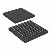
PIC32MX320F128LT-80I/BG Microchip Technology, PIC32MX320F128LT-80I/BG Datasheet - Page 9

PIC32MX320F128LT-80I/BG
Manufacturer Part Number
PIC32MX320F128LT-80I/BG
Description
128 KB Flash, 32 KB RAM, 80 MHz, 10-Bit ADC 121 XBGA 10x10x1.20mm T/R
Manufacturer
Microchip Technology
Series
PIC® 32MXr
Datasheets
1.MA320002.pdf
(208 pages)
2.DM320001.pdf
(44 pages)
3.PIC32MX320F032H-40IPT.pdf
(48 pages)
4.PIC32MX320F032H-40IPT.pdf
(66 pages)
5.PIC32MX320F032H-40IPT.pdf
(22 pages)
Specifications of PIC32MX320F128LT-80I/BG
Core Processor
MIPS32® M4K™
Core Size
32-Bit
Speed
80MHz
Connectivity
I²C, IrDA, LIN, PMP, SPI, UART/USART
Peripherals
Brown-out Detect/Reset, POR, PWM, WDT
Program Memory Size
128KB (128K x 8)
Program Memory Type
FLASH
Ram Size
16K x 8
Voltage - Supply (vcc/vdd)
2.3 V ~ 3.6 V
Data Converters
A/D 16x10b
Oscillator Type
Internal
Operating Temperature
-40°C ~ 85°C
Package / Case
121-TFBGA
Processor Series
PIC32MX3xx
Core
MIPS
3rd Party Development Tools
52713-733, 52714-737
Development Tools By Supplier
PG164130, DV164035, DV244005, DV164005, DM320001, DM320002, MA320001
Lead Free Status / RoHS Status
Lead free / RoHS Compliant
Number Of I /o
-
Eeprom Size
-
Lead Free Status / Rohs Status
Details
Available stocks
Company
Part Number
Manufacturer
Quantity
Price
Company:
Part Number:
PIC32MX320F128LT-80I/BG
Manufacturer:
Microchip Technology
Quantity:
10 000
17. Module: DMA
18. Module: Oscillator
© 2010 Microchip Technology Inc.
DMA channel abort on a channel that is not
currently active may have unintended effects on
other active channels.
Work around
1. Suspend the channel, rather than abort, by
2. Wait until other DMA channels complete
Affected Silicon Revisions
The Primary Oscillator Circuit (P
XT, XTPLL, HS and HSPLL modes, does not
operate over the voltage and temperature range
that is listed as item D5 in the device data sheet.
The operation range without the work around is
limited to -40°C through +70°C when V
Work around
Install a 4.1 MΩ resistor in parallel with the crystal.
This allows operation across the temperature
range that is listed in the data sheet.
Affected Silicon Revisions
B2
B2
X
X
clearing
DCHxCON<CHEN>.
before issuing the abort.
B3
B3
X
X
B4
B4
X
X
the
B6
B6
X
X
channel
OSC
enable
), when using
DD
< 3.0V.
bit
19. Module: PMP
20. Module: UART
The WAITE field in PMMODE<1:0> does not add
a Wait state to PMP master reads when it is
programmed to the value ‘01’. The WAITE field
allows Wait states to be added to the end of PMP
read/write operations. This field is intended to add
the following Wait clocks after the read operation
completes:
00 – no Wait states
01 – 1 Wait state
10 – 2 Wait states
11 – 3 Wait states
Current behavior is the following:
00 – no Wait states
01 – no Wait states
10 – 2 Wait states
11 – 3 Wait states
Work around
This erratum only applies to PMP master read
operations. PMP writes work correctly. Use
another Wait state control value that is allowed for
the attached device.
Affected Silicon Revisions
Using BRG values of 0, 1 or 2 cause the Start bit
to be shortened. This results in errors when
receiving the data. This issue exists for BRGH
values of ‘0’ and ‘1’.
Work around
Do not use BRG values of 0, 1 or 2. Select system
and peripheral bus clocks’ frequencies such that
the BRG value for the desired Baud Rate
Generator value is greater than 2.
Affected Silicon Revisions
B2
B2
X
X
PIC32MX3XX/4XX
B3
B3
X
X
B4
B4
X
X
B6
B6
X
X
DS80440D-page 9


