PIC24FJ16MC102-I/SS Microchip Technology, PIC24FJ16MC102-I/SS Datasheet - Page 246
PIC24FJ16MC102-I/SS
Manufacturer Part Number
PIC24FJ16MC102-I/SS
Description
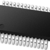
16-bit Motor Control Family, 16 MIPS, 16KB Flash, 1KB RAM 28 SSOP .209in TUBE
Manufacturer
Microchip Technology
Series
PIC® 24Fr
Datasheet
1.PIC24FJ16MC101-IP.pdf
(304 pages)
Specifications of PIC24FJ16MC102-I/SS
Processor Series
PIC24FJ
Core
PIC
Data Bus Width
16 bit
Program Memory Type
Flash
Program Memory Size
16 KB
Data Ram Size
1 KB
Maximum Operating Temperature
+ 85 C
Mounting Style
SMD/SMT
Package / Case
SSOP-28
Development Tools By Supplier
MPLAB IDE Software
Minimum Operating Temperature
- 40 C
Core Processor
PIC
Core Size
16-Bit
Speed
16 MIPs
Connectivity
I²C, IrDA, LIN, SPI, UART/USART
Peripherals
Brown-out Detect/Reset, Motor Control PWM, POR, PWM, WDT
Number Of I /o
21
Eeprom Size
-
Ram Size
1K x 8
Voltage - Supply (vcc/vdd)
3 V ~ 3.6 V
Data Converters
A/D 6x10b
Oscillator Type
Internal
Operating Temperature
-40°C ~ 85°C
Lead Free Status / Rohs Status
Details
Available stocks
Company
Part Number
Manufacturer
Quantity
Price

Part Number:
PIC24FJ16MC102-I/SS
Manufacturer:
MICROCHIP/微芯
Quantity:
20 000


PIC24FJ16MC101/102
TABLE 26-17: PLL CLOCK TIMING SPECIFICATIONS
TABLE 26-18: AC CHARACTERISTICS: INTERNAL FAST RC (FRC) ACCURACY
TABLE 26-19: INTERNAL LOW-POWER RC (LPRC) ACCURACY
DS39997B-page 246
AC CHARACTERISTICS
OS50
OS51
OS52
OS53
Note 1:
AC CHARACTERISTICS
F21a
F21b
Note 1:
Param
AC CHARACTERISTICS
F20a
F20b
Note 1:
Param
Param
No.
No.
No.
2:
3:
2:
LPRC @ 32.768 kHz
LPRC
LPRC
F
F
T
D
Symbol
PLLI
SYS
LOCK
Internal FRC Accuracy @ 7.3728 MHz
FRC
FRC
CLK
Data in “Typ” column is at 3.3V, 25°C unless otherwise stated. Parameters are for design guidance only
and are not tested.
These parameters are characterized by similarity, but are tested in manufacturing at 7.7 MHz input only.
These parameters are characterized by similarity, but are not tested in manufacturing. This specification is
based on clock cycle by clock cycle measurements. The effective jitter for individual time bases or commu-
nication clocks used by the user application, are derived from dividing the CLKO stability specification by
the square root of “N” (where “N” is equal to F
if F
Change of LPRC frequency as V
LPRC accuracy impacts the Watchdog Timer Time-out Period (T
Timer (WDT)”
Frequency calibrated at 25°C and 3.3V. TUN bits may be used to compensate for temperature drift.
OSC
Characteristic
Characteristic
PLL Voltage Controlled
Oscillator (VCO) Input
Frequency Range
On-Chip VCO System
Frequency
PLL Start-up Time (Lock Time)
CLKO Stability (Jitter)
= 32 MHz and the SPI bit rate is 5 MHz, the effective jitter of the SPI clock is equal to:
for more information.
Characteristic
(3)
(1,2)
(2)
Standard Operating Conditions: 3.0V to 3.6V (unless otherwise stated)
Operating temperature
Standard Operating Conditions: 3.0V to 3.6V (unless otherwise stated)
Operating temperature
Min
Min
-20
-30
1.5
(3)
-2
Standard Operating Conditions: 3.0V to 3.6V (unless otherwise stated)
Operating temperature
DD
changes.
±0.25
±0.25
Typ
Typ
±10
±10
(3)
(1)
Preliminary
D
------------- -
CLK
32
----- -
5
OSC
Min
3.0
Max
Max
+20
+30
12
—
-2
1.5
+2
=
divided by the peripheral data rate clock). For example,
--------- -
2.53
2%
-40°C ≤ T
-40°C ≤T
Typ
Units
Units
-40°C ≤ T
-40°C ≤T
—
—
—
=
%
%
1
-40°C ≤ T
-40°C ≤T
%
%
(1)
0.79%
A
A
≤ +85°C for Industrial
≤+125°C for Extended
-40°C ≤ T
-40°C ≤ T
-40°C ≤ T
-40°C ≤ T
WDT
Max
A
A
A
A
32
+2
8
2
≤ +85°C for Industrial
≤+125°C for Extended
≤ +85°C for Industrial
≤+125°C for Extended
1). See
A
A
A
A
Units
≤ +85°C
≤ +125°C
MHz ECPLL and MSPLL
MHz
≤ +85°C
≤ +125°C
ms
%
© 2011 Microchip Technology Inc.
Section 23.4 “Watchdog
Conditions
Conditions
modes
Conditions
—
—
—
Related parts for PIC24FJ16MC102-I/SS
Image
Part Number
Description
Manufacturer
Datasheet
Request
R

Part Number:
Description:
Manufacturer:
Microchip Technology Inc.
Datasheet:
Part Number:
Description:
Manufacturer:
Microchip Technology Inc.
Datasheet:
Part Number:
Description:
Manufacturer:
Microchip Technology Inc.
Datasheet:
Part Number:
Description:
Manufacturer:
Microchip Technology Inc.
Datasheet:
Part Number:
Description:
Manufacturer:
Microchip Technology Inc.
Datasheet:
Part Number:
Description:
Manufacturer:
Microchip Technology Inc.
Datasheet:
Part Number:
Description:
Manufacturer:
Microchip Technology Inc.
Datasheet:
Part Number:
Description:
Manufacturer:
Microchip Technology Inc.
Datasheet: