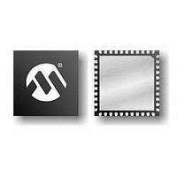
PIC16F1934-E/MV Microchip Technology, PIC16F1934-E/MV Datasheet - Page 9

PIC16F1934-E/MV
Manufacturer Part Number
PIC16F1934-E/MV
Description
7KB Flash, 256B RAM, 256B EEPROM, LCD, 1.8-5.5V 40 UQFN 5x5x0.5mm TUBE
Manufacturer
Microchip Technology
Series
PIC® XLP™ 16Fr
Datasheets
1.PIC16F722-ISS.pdf
(8 pages)
2.PIC16LF1933-ISS.pdf
(508 pages)
3.PIC16LF1933-ISS.pdf
(46 pages)
4.PIC16F1936-ISS.pdf
(2 pages)
5.PIC16F1936-ISS.pdf
(10 pages)
6.PIC16F1936-ISS.pdf
(40 pages)
7.PIC16F1936-ISS.pdf
(30 pages)
8.PIC16F1936-ISS.pdf
(12 pages)
Specifications of PIC16F1934-E/MV
Core Processor
PIC
Core Size
8-Bit
Speed
32MHz
Connectivity
I²C, LIN, SPI, UART/USART
Peripherals
Brown-out Detect/Reset, LCD, POR, PWM, WDT
Number Of I /o
36
Program Memory Size
7KB (4K x 14)
Program Memory Type
FLASH
Eeprom Size
256 x 8
Ram Size
256 x 8
Voltage - Supply (vcc/vdd)
1.8 V ~ 5.5 V
Data Converters
A/D 14x10b
Oscillator Type
Internal
Operating Temperature
-40°C ~ 125°C
Package / Case
40-UFQFN Exposed Pad
Processor Series
PIC16F
Core
PIC
Data Ram Size
256 B
Interface Type
MI2C, SPI, EUSART
Number Of Timers
5
Operating Supply Voltage
1.8 V to 5.5 V
Maximum Operating Temperature
+ 125 C
Mounting Style
SMD/SMT
Development Tools By Supplier
MPLAB IDE Software
Minimum Operating Temperature
- 40 C
Lead Free Status / RoHS Status
Lead free / RoHS Compliant
Lead Free Status / RoHS Status
Lead free / RoHS Compliant
3.1
A user may store identification information (user ID) in
four designated locations. The user ID locations are
mapped to 8000h-8003h. Each location is 14 bits in
length. Code protection has no effect on these memory
locations. Each location may be read with code
protection enabled or disabled.
REGISTER 3-1:
TABLE 3-1:
© 2008 Microchip Technology Inc.
bit 13
bit 6
Legend:
R = Readable bit
-n = Value at POR
bit 13-5
bit 4-0
Note 1:
PIC16F1933
PIC16F1934
PIC16F1936
PIC16F1937
PIC16F1938
PIC16F1939
PIC16LF1933
PIC16LF1934
PIC16LF1936
PIC16LF1937
PIC16LF1938
PIC16LF1939
Note:
DEV8
DEV1
R-q
R-q
User ID Location
This location cannot be written.
DEVICE
MPLAB
Significant bits (LSb) of each user ID
location, the upper bits are not read. It is
recommended that only the 7 LSb’s be
used if MPLAB IDE is the primary tool
used to read these addresses.
DEV<8:0>: Device ID bits
These bits are used to identify the part number.
REV<4:0>: Revision ID bits
These bits are used to identify the revision.
DEVICE ID VALUES
®
IDE only displays the 7 Least
DEVICEID: DEVICE ID REGISTER
DEV7
DEV0
R-q
R-q
P = Programmable bit
W = Writable bit
‘1’ = Bit is set
DEV6
REV4
R-q
R-q
Advance Information
10 0011 001
10 0011 010
10 0011 011
10 0011 100
10 0011 101
10 0011 110
10 0100 001
10 0100 010
10 0100 011
10 0100 100
10 0100 101
10 0100 110
DEV
DEV5
REV3
R-q
R-q
(1)
3.2
The device ID word for the PIC16F193X/LF193X is
located at 8006h. This location is read-only and can not
be erased or modified.
DEVICE ID VALUES
PIC16F193X/LF193X
U = Unimplemented bit, read as ‘0’
‘0’ = Bit is cleared
x = Bit is unknown
Device ID
DEV4
REV2
R-q
R-q
DEV3
REV1
R-q
R-q
x xxxx
x xxxx
x xxxx
x xxxx
x xxxx
x xxxx
x xxxx
x xxxx
x xxxx
x xxxx
x xxxx
x xxxx
REV
DS41360A-page 9
DEV2
REV0
R-q
R-q
bit 7
bit 0


