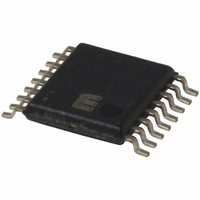
MIC2562A-0BTS TR Micrel Inc, MIC2562A-0BTS TR Datasheet - Page 5

MIC2562A-0BTS TR
Manufacturer Part Number
MIC2562A-0BTS TR
Description
PCMCIA/CardBus Socket Power Controller
Manufacturer
Micrel Inc
Type
PCMCIA/Cardbus Switchr
Datasheet
1.MIC2562A-1YM.pdf
(12 pages)
Specifications of MIC2562A-0BTS TR
Number Of Outputs
2
Rds (on)
150 mOhm
Internal Switch(s)
Yes
Current Limit
1.5A
Voltage - Input
3.3V, 5V, 12V
Operating Temperature
-40°C ~ 85°C
Mounting Type
Surface Mount
Package / Case
16-TSSOP
Lead Free Status / RoHS Status
Contains lead / RoHS non-compliant
Other names
MIC2562A-0BTSTR
MIC2562A-0BTSTR
MIC2562A-0BTSTR
V
“C,” V
programmed to 5V. At “H,” V
measurements. Load capacitance is negligible.
V
3.3V. At “B,” V
is 10k to V
June 2004
MIC2562A
PP
CC
Enable is shown generically: refer to the timing tables. At time “A,” V
Enable is shown generically: refer to the timing tables for specific control logic input. At time “A,” V
PP
= 3.3V (from 12V). At “D,” V
CC3
CC
IN.
is disabled. At “C,” V
V
Enable
V
Output
3.3V
12V
PP
PP
/FLAG
5V
0
0
A
t
V CC
Output
/FLAG
1
V CC
Enable
to 3.3V
V
PP
3.3V
t
PP
4
5V
0
0
0
B
is disabled. At “J,” V
A
t
7
to 12V
t 1
V
PP
V CC to 3.3V
PP
CC
t 3
is disabled. At “E,” V
Figure 2. MIC2562A V
Figure 1. MIC2562A V
is programmed to 5V. And at “D,” V
C
to 3.3V
t
V
9
PP
t
14
D
V
OFF
B
PP
t
11
t 7
E
t
PP
2
V CC OFF
t 5
to 5V
is set to 12V. And at “K,” V
t
V
5
PP
PP
5
F
is programmed to 5V. At “F,” V
CC
PP
C
t 2
t
Timing Diagram
Timing Diagram
8
V CC to 5V
to 12V
V
PP
t 4
PP
G
CC
= 3.3V is selected. At “B,” V
to 5V
t
V
10
is disabled. R
PP
D
t 8
PP
V CC OFF
H
OFF
V
is again disabled. R
PP
t
15
t
12
t 6
J
t
3
to 12V
t
L
V PP
6
PP
= 10 . FLAG pull-up resistor
is set to 12V. At “G,” V
K
OFF
t
V
t
16
13
PP
CC
PP
is programmed to
is set to 12V. At
L
= 100
M9999-062204
Micrel
for all
PP
is


