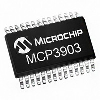
MCP3903T-E/SS Microchip Technology, MCP3903T-E/SS Datasheet - Page 24

MCP3903T-E/SS
Manufacturer Part Number
MCP3903T-E/SS
Description
Six Channel Energy Meter Front End, SPI Interface 28 SSOP .209in T/R
Manufacturer
Microchip Technology
Series
-r
Datasheet
1.MCP3903-ISS.pdf
(54 pages)
Specifications of MCP3903T-E/SS
Number Of Bits
24
Number Of Channels
6
Power (watts)
-
Voltage - Supply, Analog
4.5 V ~ 5.5 V
Voltage - Supply, Digital
2.7 V ~ 3.6 V
Package / Case
28-SSOP (0.209", 5.30mm Width)
Lead Free Status / Rohs Status
Lead free / RoHS Compliant
MCP3903
5.3.2
For a specified voltage reference value of 2.4V, the
modulator specified differential input range is ±500 mV.
The input range is proportional to V
according to the V
stability of the modulator over amplitude and frequency.
Outside of this range, the modulator is still functional,
however its stability is no longer guaranteed and
therefore it is not recommended to exceed this limit.
The saturation point for the modulator is V
the transfer function of the ADC includes a gain of 3 by
default (independent from the PGA setting. See
Section 5.5 “ADC OUTPUT
5.3.3
The
independent BOOST mode for each channel. If the
corresponding BOOST<1:0> bit is enabled, the power
consumption of the modulator is multiplied by 2 and its
bandwidth is increased to be able to sustain AMCLK
clock frequencies up to 8.192 MHz while keeping the
ADC accuracy. When disabled, the power consumption
returns back to normal and the AMCLK clock
frequencies can only reach up to 5 MHz without
affecting ADC accuracy.
DS25048B-page 24
Delta-Sigma
MODULATOR INPUT RANGE AND
SATURATION POINT
BOOST MODE
REF
modulators
voltage. This range ensures the
CODING”).
also
REF
include
REF
and scales
/3 since
an
© 2011 Microchip Technology Inc.


