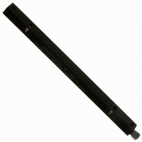
Z3A45SBSBNR CTS Thermal Management Products, Z3A45SBSBNR Datasheet - Page 3

Z3A45SBSBNR
Manufacturer Part Number
Z3A45SBSBNR
Description
PCB RETAINER 4.5" HEX-HEAD ROD
Manufacturer
CTS Thermal Management Products
Series
ZIF IIIr
Datasheet
1.Z3A45SBSBNR.pdf
(24 pages)
Specifications of Z3A45SBSBNR
Accessory Type
PCB Retainer, 4.5", Right Hand
For Use With/related Products
PCB Mounting
Lead Free Status / RoHS Status
Lead free / RoHS Compliant
Other names
294-1164
ADHESIVE PEEL AND STICK HEAT SINKS
•
•
•
•
•
•
•
NOTES:
***
**
messy adhesives or greases required
Adhesive shear strength at 100°C is
require a 36lb. force to remove heat sink)
Applicable for BGA, PGA, PLCC,
and QFP packages
With pre-applied adhesive, just peel
off the release liner and press onto the
component
Reduces assembly costs; no more
Excellent mechanical bond
Thermally optimized pin fin
Omnidirectional
36psi (a one inch square heat sink would
*
Part numbers
Thermal resistance
Thermal resistance
of adhesive tape is
included.
values based on
power density of
3 watts/in.
listed for standard
black anodized
heat sinks with
CTS adhesive
tapes.
2
All dimensions are in inches.
BDN09-3CB/A01
BDN09-6CB/A01
BDN10-3CB/A01
BDN10-5CB/A01
BDN11-3CB/A01
BDN11-6CB/A01
BDN12-3CB/A01
BDN12-5CB/A01
BDN13-3CB/A01
BDN13-5CB/A01
BDN14-3CB/A01
BDN14-6CB/A01
BDN15-3CB/A01
BDN15-5CB/A01
BDN16-3CB/A01
BDN16-6CB/A01
BDN17-3CB/A01
BDN17-5CB/A01
BDN18-3CB/A01
BDN18-6CB/A01
BDN19-3CB/A01
BDN19-5CB/A01
BDN20-3CB/A01
BDN20-5CB/A01
BDN21-3CB/A01
BDN21-6CB/A01
PART NUMBER ***
HEAT SINK
0.91
1.01
1.11
1.21
1.31
1.41
1.51
1.61
1.71
1.81
1.91
2.01
2.11
(W)
HEAT SINK SPECIFICATIONS
H±0.015
0.91
1.01
1.11
1.21
1.31
1.41
1.51
1.61
1.71
1.81
1.91
2.01
2.11
(L)
SIZE
.355
.605
.355
.555
.355
.605
.355
.555
.355
.555
.355
.605
.355
.555
.355
.605
.355
.555
.355
.605
.355
.555
.355
.555
.355
.605
(H)
.09
.10
.09
.10
.09
.10
.09
.10
.09
.10
.09
.10
.09
.10
.09
.10
.09
.10
.09
.10
.09
.10
.09
.10
.09
.10
G±0.01
T
L±0.01
.069
.132
.083
.111
.076
.119
.060
.105
.074
.125
.067
.128
.062
.118
.072
.119
.065
.114
.072
.128
.069
.111
.066
.122
.064
.120
PIN FIN CONFIGURATION
P
.072
.128
.072
.114
.072
.128
.081
.114
.081
.114
.081
.128
.081
.114
.081
.128
.072
.114
.072
.114
.072
.114
.072
.114
.072
.128
G
MATRIX
10x10
13x13
13x13
14x14
15x15
16x16
11x11
11x11
7x7
4x4
7x7
5x5
8x8
5x5
9x9
6x6
9x9
6x6
6x6
7x7
7x7
8x8
8x8
9x9
9x9
9x9
FIN
W±0.01
P±0.01
CASE TO AMBIENT * °C/WATTS
CONVECTION **
NATURAL
THERMAL RESISTANCE
26.9
24.5
26.4
20.8
20.9
18.5
19.6
16.5
16.1
14.9
16.2
13.1
15.1
13.5
10.6
10.8
11.9
11.5
T±0.01
9.5
8.1
9.9
7.8
9.1
7.2
8.5
6.5
CTS
CONVECTION
@ 400 LFPM
FORCED
9.6
7.7
8.0
6.3
7.2
5.7
6.8
5.2
6.0
4.7
5.6
4.2
4.5
3.8
4.5
3.5
3.8
3.2
3.5
2.8
2.9
2.7
2.8
2.5
2.6
2.2
3
®


