CMS2-4-R Cooper/Bussmann, CMS2-4-R Datasheet - Page 3
CMS2-4-R
Manufacturer Part Number
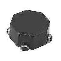
CMS2-4-R
Description
Common Mode Inductors (Chokes) 102uH 2.8A 0.019ohms
Manufacturer
Cooper/Bussmann
Series
CMSr
Type
Common Moder
Datasheet
1.CMS2-4-R.pdf
(4 pages)
Specifications of CMS2-4-R
Inductance
102 uH
Maximum Dc Current
2.8 Amps
Maximum Dc Resistance
0.019 Ohms
Operating Temperature Range
- 40 C to + 160 C
Termination Style
SMD/SMT
Product
Inductors
Core Material
Ferrite
Dimensions
8.89 mm W x 11.43 mm L x 6 mm H
Shielding
Unshielded
Impedance
Not RequiredOhm
Dc Resistance
19mOhm
Operating Temp Range
-40C to 160C
Test Frequency
100KHz
Dc Current
2.8A
Product Diameter (mm)
Not Requiredmm
Product Height (mm)
6mm
Product Depth (mm)
11.43mm
Product Length (mm)
11.43mm
Military Standard
Not Required
Failure Rate
Not Required
Lead Free Status / RoHS Status
Lead free / RoHS Compliant
Lead Free Status / RoHS Status
Lead free / RoHS Compliant
Available stocks
Company
Part Number
Manufacturer
Quantity
Price

Part Number:
CMS2-4-R
Manufacturer:
COOPER
Quantity:
20 000


Packaging Information
CMS1 Series
CMS3 Series
Attenuation Curves
Ao= 7.3mm
Bo= 10.1mm
Ko= 2.7mm
0.3Rad
max.
-10
-15
-20
-25
-30
-35
-10
-15
-20
-25
-30
-35
-40
-45
-50
-5
-5
0
0
SECTION A-A
1
1
Ko
-11
-11
+/-0.05
2
Attenuation
1.5 Dia
-11
.30
-11
2
-14
min.
-14
Bo
-14
4
-14
4
Ao
FREQUENCY (MHz)
6
6
Ao=11.8mm
Bo=11.8mm
Ko=6.8mm
See note 6
See note 1
12.0
CMS 1
2.0
8
4.0
-1
8
-1 -4
CMS & CMT Product Family
10
Attenuation Curves
1.5 Dia.
+0.1/-0.0
0.3Rad
-4
-1
A
A
Series
max.
-1 -4
CMS & CMT Product Family
SECTION A-A
10
Direction of feed
+/-0.05
-10
-15
-20
-25
-30
-35
-40
-45
-50
0.35
Attenuation Curves
-7
20
-4
-5
0
-7
1
-7
-11
-11
20
-7
7.1
K
40
Pin #1 indicator
0.5Rad
typ.
Attenuation
+0.1/-0.0
2
B
-14
1.5 dia
1.75
See note 6 16.0
-14
60
40
7.5
4
FREQUENCY (MHz)
+/-0.3
A
(see note 6)
Pin #1 Indicator
6
2.0
CMS 3
CMS2 Series
Ao=9.3mm
Bo=9.3mm
Ko=6.4mm
-1
8
-1 -4
CMS & CMT Product Family
Attenuation Curves
-4
(see note 1)
Series
16.0
10
-10
-15
-20
-25
-30
-35
-40
-45
-50
4.0
-10
-20
-30
-40
-50
-60
-70
-7
-5
0.3Rad
0
1.5 dia
min
max.
0
-7
-1 -2 -3
-11
0.06
1
SECTION A-A
+/-0.05
0.30
User direction of feed
-6 -7 -8 -9
20
-1 -2 -3
-11
-14
A
2
A
Attenuation
-6 -7 -8 -9
K
6.7
0.1
-14
-4 -5
40
+0.1/-0.0
B
1.5 dia
0.5 rad
typ
4
-4 -5
0.2
-10
FREQUENCY (MHz)
(see note 6)
1.75
Common Mode Inductors
(see note 6)
11.5
6
A
-10
Pin #1 Indicator
2.0
0.6
CMS 2
+/-0.3
-1
24.0
8
-4 -7
-1
(see note 1)
12.0
1
10
4.0
-10
-20
-30
-40
-50
-60
-70
-4 -7
Series
0
0.06
(Surface Mount)
1.5 dia
min
20
-1 -2 -3
2
-11
CMS-SERIES
User direction of feed
-6 -7 -8 -9
0.1
-14
40
A
4
A
-4 -5
60
0.2
0.5 rad
typ
(see note 6)
1.75
11.5
-10
0.6
+/-0.3
24.0
-1
1
-4 -7
2
Related parts for CMS2-4-R
Image
Part Number
Description
Manufacturer
Datasheet
Request
R

Part Number:
Description:
INDUCTOR COMMON MODE 25UH SMD
Manufacturer:
Coiltronics/Div of Cooper/Bussmann
Part Number:
Description:
INDUCTOR COMMON MODE 575UH SMD
Manufacturer:
Coiltronics/Div of Cooper/Bussmann
Part Number:
Description:
INDUCTOR COMMON MODE 700UH SMD
Manufacturer:
Coiltronics/Div of Cooper/Bussmann
Part Number:
Description:
INDUCTOR COMMON MODE 915UH SMD
Manufacturer:
Coiltronics/Div of Cooper/Bussmann
Part Number:
Description:
INDUCTOR COMMON MODE 1070UH SMD
Manufacturer:
Coiltronics/Div of Cooper/Bussmann
Part Number:
Description:
INDUCTOR COMMON MODE 1340UH SMD
Manufacturer:
Coiltronics/Div of Cooper/Bussmann
Datasheet:
Part Number:
Description:
INDUCTOR COMMON MODE 57UH SMD
Manufacturer:
Coiltronics/Div of Cooper/Bussmann
Part Number:
Description:
INDUCTOR COMMON MODE 160UH SMD
Manufacturer:
Coiltronics/Div of Cooper/Bussmann
Part Number:
Description:
INDUCTOR COMMON MODE 230UH SMD
Manufacturer:
Coiltronics/Div of Cooper/Bussmann
Part Number:
Description:
INDUCTOR COMMON MODE 270UH SMD
Manufacturer:
Coiltronics/Div of Cooper/Bussmann
Datasheet:

Part Number:
Description:
Manufacturer:
Cooper/Bussmann
Datasheet: