CMS2-4-R Cooper/Bussmann, CMS2-4-R Datasheet

Common Mode Inductors (Chokes) 102uH 2.8A 0.019ohms

CMS2-4-R

Manufacturer Part Number
CMS2-4-R
Description
Common Mode Inductors (Chokes) 102uH 2.8A 0.019ohms
Manufacturer
Cooper/Bussmann
Series
CMSr
Type
Common Moder
Datasheet

Specifications of CMS2-4-R

Inductance
102 uH
Maximum Dc Current
2.8 Amps
Maximum Dc Resistance
0.019 Ohms
Operating Temperature Range
- 40 C to + 160 C
Termination Style
SMD/SMT
Product
Inductors
Core Material
Ferrite
Dimensions
8.89 mm W x 11.43 mm L x 6 mm H
Shielding
Unshielded
Impedance
Not RequiredOhm
Dc Resistance
19mOhm
Operating Temp Range
-40C to 160C
Test Frequency
100KHz
Dc Current
2.8A
Product Diameter (mm)
Not Requiredmm
Product Height (mm)
6mm
Product Depth (mm)
11.43mm
Product Length (mm)
11.43mm
Military Standard
Not Required
Failure Rate
Not Required
Lead Free Status / RoHS Status
Lead free / RoHS Compliant
Lead Free Status / RoHS Status
Lead free / RoHS Compliant

Available stocks

Company
Part Number
Manufacturer
Quantity
Price
Part Number:
CMS2-4-R
Manufacturer:
COOPER
Quantity:
20 000
Description
• 160°C maximum total temperature
• Three sizes of surface mount torroidal common
• Inductance range from 5.5uH to 1600uH
• Current range up to 7.0 Amps
• Noise attenuation up to 44 dB
• Frequency range up to 100 MHz
• Meets UL94V-0 flammability standard
• Ferrite core material
Applications
• EMI filters
• DC-DC brick power supplies
• Discrete output supplies
• Discrete and point-of-use power supplies (PUPS)
Environmental Data
• Storage temperature range: -40°C to +160°C
• Operating ambient temperature range: -40°C to +160°C
• Solder reflow temperature: +260°C max for 10 seconds
Definitions:
OCL = Open Circuit Inductance
DCR = Direct Current Resistance
Irms = rms current for approx. a 40°C temperature rise at an ambient temperature of 85°C.
*Operating Temperature: 160°C Max. Inductance values are sustained up to 160°C.
mode inductors that provide 300Vdc isolation
(range is application specific)
max.
Part Number
CMS1-10-R
CMS1-11-R
CMS1-12-R
CMS1-13-R
CMS1-14-R
CMS2-10-R
CMS2-11-R
CMS2-12-R
CMS2-13-R
CMS2-14-R
CMS1-1-R
CMS1-2-R
CMS1-3-R
CMS1-4-R
CMS1-5-R
CMS1-6-R
CMS1-7-R
CMS1-8-R
CMS1-9-R
CMS2-1-R
CMS2-2-R
CMS2-3-R
CMS2-4-R
CMS2-5-R
CMS2-6-R
CMS2-7-R
CMS2-8-R
CMS2-9-R
CMS3-1-R
CMS3-2-R
CMS3-3-R
(uH) minimum
(1-2) & (3-4)
1070
1340
OCL
12.6
32.8
41.5
51.2
73.7
100
131
166
205
102
160
230
270
360
460
575
700
915
4.5
18
25
62
25
40
57
28
45
64
8
Amperes
I rms.
Max *
7.00
5.70
4.10
3.80
3.60
3.10
2.60
2.20
1.90
1.65
1.35
1.15
1.00
0.85
5.35
4.40
3.60
2.80
2.30
1.85
1.60
1.35
1.10
0.94
0.80
0.67
0.58
0.50
5.70
5.10
4.75
2002/95/EC
DCR (Ω) typ
RoHS
@ 20°C
0.0027
0.0040
0.0077
0.0089
0.0100
0.0138
0.019
0.026
0.035
0.048
0.070
0.100
0.138
0.186
0.005
0.008
0.012
0.019
0.029
0.044
0.060
0.084
0.120
0.170
0.230
0.330
0.440
0.620
0.005
0.006
0.007
(1-2)
Electrical Characteristics:
OCL (1-2) 0.10Vrms, 100kHz, 0.0Adc: (See Chart)
OCL (4-3) 0.10Vrms, 100kHz, 0.0Adc: (See Chart)
DCR (1-2) typ @ 20°C: (See Chart)
DCR (4-3) typ @ 20°C: (See Chart)
Hipot rating: winding to winding: 300Vdc min. for 1 second.
Turns Ratio: (1-2):(4-3) 1:1
Packaging
• Supplied in tape and reel packaging, 2,000 (CMS1),
800 (CMS2), and 600 (CMS3) per reel
DCR (Ω) typ
@ 20°C
0.0027
0.0040
0.0077
0.0089
0.0100
0.0138
0.019
0.026
0.035
0.048
0.070
0.100
0.138
0.186
0.005
0.008
0.012
0.019
0.029
0.044
0.060
0.084
0.120
0.170
0.230
0.330
0.440
0.620
0.005
0.006
0.007
(4-3)
Common Mode Inductors
Inductance (uH)
Leakage
0.056
0.05
0.09
0.14
0.20
0.28
0.36
0.45
0.68
0.81
1.10
1.45
1.83
2.25
0.22
0.34
0.47
0.80
1.25
1.75
2.00
2.60
3.30
4.00
5.00
6.30
7.30
9.00
0.31
0.46
0.64
typ
(Surface Mount)
CMS-SERIES
Capacitance (pF)
Interwinding
2.80
3.05
3.30
typ
2.0
2.1
2.2
2.3
2.4
2.5
2.6
2.7
2.7
2.8
2.9
3.0
3.1
3.2
2.0
2.3
2.5
2.8
3.1
3.4
3.6
3.9
4.1
4.3
4.6
4.9
5.1
5.4

Related parts for CMS2-4-R

CMS2-4-R Summary of contents

Page 1

... CMS1-7-R 41.5 CMS1-8-R 51.2 CMS1-9-R 62 CMS1-10-R 73.7 CMS1-11-R 100 CMS1-12-R 131 CMS1-13-R 166 CMS1-14-R 205 CMS2-1-R 25 CMS2-2-R 40 CMS2-3-R 57 CMS2-4-R 102 CMS2-5-R 160 CMS2-6-R 230 CMS2-7-R 270 CMS2-8-R 360 CMS2-9-R 460 CMS2-10-R 575 CMS2-11-R 700 CMS2-12-R 915 CMS2-13-R 1070 CMS2-14-R 1340 CMS3-1-R ...

Page 2

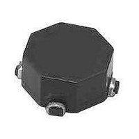
... Mechanical Diagrams CMS1 Series TOP VIEW 9.4 max CMS1- 7.2 max wwllyy Pin 1 indicator White dot F 2 CMS2 Series CMS3 Series wwllyy = Date code R = Revision level I rms. DCR (Ω) typ DCR (Ω) typ Amperes @ 20°C @ 20°C Max * (1-2) 3.95 0.010 3.10 0.017 2 ...

Page 3

... FREQUENCY (MHz -10 -15 -20 -25 -30 -35 -40 -45 -11 -11 -14 -14 - CMS2 Series 1.5 Dia. Pin #1 indicator +0.1/-0.0 1.75 A Ao=9.3mm 7.5 0.3Rad max. See note 6 16.0 Bo=9.3mm +/-0.3 Ko=6.4mm A 0.5Rad typ. Direction of feed 4.0 (see note 1) 2.0 1.5 dia (see note 6) 1.5 dia min 0 ...

Page 4

... CMS-SERIES Common Mode Inductors (Surface Mount) Impedance CMS1 - 7,11, & 14 -14 -11 -7 0.6 0 FREQUENCY (MHz) Impedance CMS2 - 7,11, & 0.6 0 FREQUENCY (MHz) Impedance CMS3 - 7,11, & 14 -14 -11 -7 0.6 0 FREQUENCY (MHz) 6 ...

Related keywords