2058302-1 TE Connectivity, 2058302-1 Datasheet - Page 7
2058302-1
Manufacturer Part Number
2058302-1
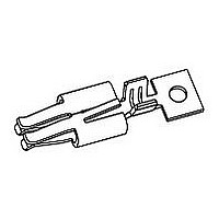
Description
SOCKET CONTACT
Manufacturer
TE Connectivity
Datasheet
1.1-2058703-1.pdf
(8 pages)
Specifications of 2058302-1
Connector Type
Contact, Crimp
Current Rating
5A
Contact Plating
Tin
Contact Material
Copper Alloy
Contact Size
18
Contact Gender
Socket
Contact
RoHS Compliant
Contact Termination
Crimp
Rohs Compliant
Yes
Product
Blade Terminals
Wire Size (awg)
22-18
Insulation
Not Insulated
Gender
Male
Termination Style
Crimp
Mounting Angle
Straight
Mounting Method
Wire
Number Of Positions / Contacts
1
Number Of Rows
1
Voltage Rating
125 V
Product Type
Contact
Wire/cable Type
Discrete Wire
Termination Method To Wire/cable
Crimp
Keyed
No
Make First / Break Last
No
Contact Current Rating, Max (a)
5
Wire/cable Size (awg)
18 – 22
Profile Height (y-axis) (mm [in])
3.00 [0.118]
Length (x-axis) (mm [in])
11.90 [0.468]
Width (z-axis) (mm [in])
4.70 [0.185]
Contact Type
Socket
Contact Plating, Mating Area, Material
Matte Tin
Stamped And Formed
Yes
Pre-designed Cables Available
Yes
Rohs/elv Compliance
RoHS compliant, ELV compliant
Lead Free Solder Processes
Not relevant for lead free process
Rohs/elv Compliance History
Always was RoHS compliant
Circuit Identification Feature
Without
Applies To
Wire/Cable
Glow Wire Rating
No
Uv Exposure Rated
No
Application Use
Wire-to-Board
Packaging Method
Strip
For Use With
Hermaphroditic Wire-to-Board
Lead Free Status / Rohs Status
Details


5.1. Hand Crimping Tools
Hand crimping tools that accommodate the full wire size range are designed for prototype and low volume
applications.
5.2. Applicators
Applicators are designed for the full wire size range of strip--fed, precision formed contacts, and provide for
high volume, heavy duty production requirements. The applicators can be used in bench or floor model power
units. See Figure 8.
5.3. Power Units
A power unit is an automatic or semi--automatic machine used to assist in the application of a product. Power
units provide the force required to drive the applicator. See Figure 8.
5.4. Extraction Tools
Extraction tools are designed to release the locking lance inside the connector housing without damaging the
housing or contacts. Customers may use their own extraction tools, in which case the tool must fit in a
1.10 x 0.70 mm opening in the housing. The tool must be long enough to release the locking lance which is
located at a depth of 10.50 mm in the housing.
Rev E
Heavy Duty Mini (HDM)
Side Feed Applicator
NOTE
NOTE
i
i
SIZE (AWG)
22
20
18
TE Tool Engineers have designed machines for a variety of application requirements. For assistance in setting up
prototype and production line equipment, contact TE Tool Engineering through your local TE Representative, or call
the Tooling Assistance Center number at the bottom of page 1.
Each applicator is shipped with a metal identification tag attached. DO NOT remove this tag or disregard the
information on it. Also, a packet of associated paperwork is included in each applicator shipment. This information
should be read before using the applicator; then it should be stored in a clean, dry area near the applicator for future
reference. Some changes may have to be made to the applicators to run in all related power units. Contact the Tooling
Assistance Center number located at the bottom of page 1 for specific changes.
WIRE
INSULATION DIA.
1.65--2.03
1.65--2.03
1.65--2.03
1852817--3 (408--8040)
85 8
APPLICATOR
Figure 8
3 ( 08 80 0)
PRO- - CRIMPER III
Hand Tool Assembly
2063778- - 1 with Die
Assembly 2063778- - 2
AMP- - O- - LECTRIC
Model “G” Terminating
Machine 354500- - [ ]
TOOLING (DOCUMENT)
354500--1 (409--5842)
35 500
POWER UNIT
( 09 58 )
2063778--1 (408--10290)
063 8
HAND TOOL
( 08 0 90)
114- 13252
7 of 8
Related parts for 2058302-1
Image
Part Number
Description
Manufacturer
Datasheet
Request
R

Part Number:
Description:
Printers THERMAL PRINTER HS-SLEEVE MARKER
Manufacturer:
TE Connectivity


Part Number:
Description:
High Speed / Modular Connectors 30P HEADER ASSY
Manufacturer:
TE Connectivity
Datasheet:

Part Number:
Description:
High Speed / Modular Connectors REC 6X005P R/A LT B-PLANE HS3
Manufacturer:
TE Connectivity
Datasheet:

Part Number:
Description:
High Speed / Modular Connectors 2MM HM RCPT 50P R/A AU
Manufacturer:
TE Connectivity
Datasheet:

Part Number:
Description:
High Speed / Modular Connectors 2MM HM RCPT 50P R/A AU
Manufacturer:
TE Connectivity
Datasheet:


Part Number:
Description:
Manufacturer:
TE Connectivity
Datasheet:


Part Number:
Description:
Manufacturer:
TE Connectivity
Datasheet:

Part Number:
Description:
Manufacturer:
TE Connectivity
Datasheet:

Part Number:
Description:
Manufacturer:
TE Connectivity
Datasheet: