2058302-1 TE Connectivity, 2058302-1 Datasheet

SOCKET CONTACT

2058302-1

Manufacturer Part Number
2058302-1
Description
SOCKET CONTACT
Manufacturer
TE Connectivity
Datasheet

Specifications of 2058302-1

Connector Type
Contact, Crimp
Current Rating
5A
Contact Plating
Tin
Contact Material
Copper Alloy
Contact Size
18
Contact Gender
Socket
Contact
RoHS Compliant
Contact Termination
Crimp
Rohs Compliant
Yes
Product
Blade Terminals
Wire Size (awg)
22-18
Insulation
Not Insulated
Gender
Male
Termination Style
Crimp
Mounting Angle
Straight
Mounting Method
Wire
Number Of Positions / Contacts
1
Number Of Rows
1
Voltage Rating
125 V
Product Type
Contact
Wire/cable Type
Discrete Wire
Termination Method To Wire/cable
Crimp
Keyed
No
Make First / Break Last
No
Contact Current Rating, Max (a)
5
Wire/cable Size (awg)
18 – 22
Profile Height (y-axis) (mm [in])
3.00 [0.118]
Length (x-axis) (mm [in])
11.90 [0.468]
Width (z-axis) (mm [in])
4.70 [0.185]
Contact Type
Socket
Contact Plating, Mating Area, Material
Matte Tin
Stamped And Formed
Yes
Pre-designed Cables Available
Yes
Rohs/elv Compliance
RoHS compliant, ELV compliant
Lead Free Solder Processes
Not relevant for lead free process
Rohs/elv Compliance History
Always was RoHS compliant
Circuit Identification Feature
Without
Applies To
Wire/Cable
Glow Wire Rating
No
Uv Exposure Rated
No
Application Use
Wire-to-Board
Packaging Method
Strip
For Use With
Hermaphroditic Wire-to-Board
Lead Free Status / Rohs Status
 Details
1. INTRODUCTION
This specification covers the requirements for the application of the Wire--to--Board Connectors which mate
with Hermaphroditic Blade and Receptacle SMT Connectors. The contacts will accept stranded copper wire
with a wire size range of 22--18 AWG. The contacts feature a locking lance to engage the housing and require
no insertion tooling. Once terminated, the contacts are inserted into the BACK of the housings. The housings
have single row cavities with a centerline spacing of 4.00 mm and are available in 2, 4, and 6 positions. The
housing is available in two colors, natural and black. The housing has a latch which engages with a tab on the
Hermaphroditic Blade and Receptacle Connector.
When corresponding with TE Personnel, use the terminology provided on this specification to help facilitate
your inquiry for information. Basic terms and features of components are provided in Figure 1.
2. REFERENCE MATERIAL
2.1. Revision Summary
2.2. Customer Assistance
Reference base part number 2058299 and product code L012 are representative numbers of the
Wire--to--Board Connector. Use of these numbers will identify the product line and expedite your inquiries
through a service network established to help you obtain product and tooling information. Such information can
be obtained through a local TE Representative or, after purchase, by calling the Tooling Assistance Center or
the Product Information number at the bottom of this page.
2.3. Drawings
Customer Drawings for specific products are available from the responsible TE Engineering Department via the
service network. The information contained in the Customer Drawings takes priority if there is a conflict with
this specification or with any other technical documentation supplied by TE.
E2011 Tyco Electronics Corporation, a TE Connectivity Ltd. Company
All Rights Reserved
TE logo is a trademark.
*Trademark. Other product names, logos, or company names might be trademarks of their respective owners.
Refer to Application Specification
114- - 13225 for Application
Requirements for the Hermaphroditic
Blade and Receptacle Connector
NOTE
S
i
Updated document to corporate requirements
All numerical values are in metric units [with U.S. customary units in brackets]. Dimensions are in millimeters [and
inches]. Unless otherwise specified, dimensions have a tolerance of +0.13 [+.005] and angles have a tolerance of +2_.
Figures and illustrations are for identification only and are not drawn to scale.
Wire- to- Board Connector
for Hermaphroditic Blade and
Receptacle SMT Connectors
TOOLING ASSISTANCE CENTER 1--800--722--1111
PRODUCT INFORMATION 1--800--522--6752
Housing
Figure 1
Locking Latch
Socket Contact
This controlled document is subject to change.
For latest revision and Regional Customer Service,
visit our website at www.te.com
Blade Contact
Application Specification
114- - 13252
16 Mar 11 Rev E
1 of 8
LOC B

Related parts for 2058302-1

2058302-1 Summary of contents

Page 1

... Customer Drawings for specific products are available from the responsible TE Engineering Department via the service network. The information contained in the Customer Drawings takes priority if there is a conflict with this specification or with any other technical documentation supplied by TE. E2011 Tyco Electronics Corporation Connectivity Ltd. Company All Rights Reserved TE logo is a trademark. ...

Page 2

Specifications Design Objective 108--2387 provides expected product performance and test information. Application Specification 114--13225 provides information on Hermaphroditic Blade and Receptacle Connectors. 2.5. Instructional Material The following list includes instruction sheets (408--series) that provide assembly procedures for product, operation, ...

Page 3

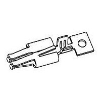
Contact Crimping Contacts accept stranded wire only. Strip form contacts are designed to be crimped with a miniature applicator in a semi--automatic or automatic machine and loose--piece contacts may be crimped using a hand tool. Refer to the table ...

Page 4

Socket Contact Shown, Blade Contact Has Same Requirements Locking Lance Not Deformed Wire Barrel Crimp Width 0.10 Max. Wire Barrel Flash Section Twist and Roll There shall be no twist or roll in crimped portion that will ...

Page 5

K. Straightness The contact, including the cutoff tab, shall not be bent above or below the datum line more than the amount shown in Figure 5. Socket Contact Shown, Blade Contact Has Same Requirements Side- - to- - Side Up- ...

Page 6

B. Engagement The mating connectors must have an identical number of circuit positions. Polarizing features must be properly oriented. Insert the Wire--to--Board Connector straight towards Hermaphroditic Connector until it bottoms and the locking latch and locking tab engage. See Figure ...

Page 7

TE Tool Engineers have designed machines for a variety of application requirements. For assistance in setting up NOTE prototype and production line equipment, contact TE Tool Engineering through your local TE Representative, or call i the Tooling Assistance Center number ...

Page 8

VISUAL AID Figure 9 shows a typical application of a Wire--to--Board Connector and contact. This illustration should be used by production personnel to ensure a correctly applied product. Applications which DO NOT appear correct should be inspected using the ...

Related keywords