203618-1 TE Connectivity, 203618-1 Datasheet - Page 19
203618-1
Manufacturer Part Number
203618-1
Description
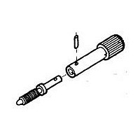
Connector Accessories Male Jack Screw Zinc Alloy
Manufacturer
TE Connectivity
Type
Jack Screw Kitr
Series
Mr
Specifications of 203618-1
Product Length (mm)
47.19mm
Product Depth (mm)
7.92mm
Product Diameter (mm)
7.92mm
Accessory Type
Jack Screw
Thread Size - Imperial
6-32
Screw Head Height
9.91mm
Screw Length
47.19mm
Screw Head Diameter
0.312"
Rohs Compliant
Yes
Angle
Straight
Brand/series
M Series
Length, Overall
1.858 "
Material, Housing
Zinc Alloy
Primary Type
Interconnect System
Product Type
Hardware
Gender
Male
Type Of Connector
Standard
Mount
Panel
Jackscrew Type
Turnable
Jackscrew Material
Zinc Alloy
Hardware Type
Jackscrew
Mounting Hardware
None
Jackscrew Style
Short
Jackscrew Coating
Clear Chromate
Jackscrew Tip, Roll Pin Material
Stainless Steel
Rohs/elv Compliance
RoHS compliant, ELV compliant
Lead Free Solder Processes
Not relevant for lead free process
Rohs/elv Compliance History
Always was RoHS compliant
Packaging Method
Loose Piece
Lead Free Status / RoHS Status
Compliant
For Use With
M Series Rectangular Connectors
Lead Free Status / Rohs Status
RoHS Compliant part


1.
2. Find the appropriate column for the number of positions
3. Select part numbers required for the application listed
4. Dimensional information is available on the indicated
5. Select Contacts: Type II (page 30), Type III+ (pages 31
Catalog 82003
Revised 06-08
www.tycoelectronics.com
200390-9
200389-2
202135-2
202135-4
201302-3
201302-1
201766-1
201922-1
201921-1
Confirm that Application E (at left) most closely meets
your requirements. (Other applications are shown on
pages 10-17 and 20 through 25.)
required.
in the column below the number of positions.
If a part number is not listed for a particular item, it is
not available.
If more than one part number is listed for a particular
hardware item, choose the one which best fits your appli-
cation.
pages under description column.
through 35) or Subminiature Coaxial (pages 40, 41).
41
—
—
—
—
—
—
—
—
—
—
—
1-200833-1
1-200835-1
200277-4
200389-2
200390-9
200277-2
201358-3
201358-1
201182-4
201847-1
201925-1
201926-1
50
—
—
—
—
—
—
—
—
Dimensions are in millimeters
and inches unless otherwise
specified. Values in brackets are
equivalent U.S. Customary Units.
75
—
—
—
—
—
—
—
—
—
—
—
—
—
—
—
—
—
—
—
—
Cable-to-Panel
Number of Positions
AMP M Series
Pin and Socket Connectors
104
—
—
—
—
—
—
—
—
—
—
—
—
—
—
—
—
—
—
—
—
1-201692-6
Dimensions are shown for
reference purposes only.
Specifications subject
to change.
104 CF
—
—
—
—
—
—
—
—
—
—
—
—
—
—
—
—
—
—
—
(Continued)
Special application housings and posted housings may be
substituted for these standard housings. See Special
Application and Posted Connectors Sections.
This cable-to-panel application utilizes locking springs, strain
relief clamps, a pin hood for pin protection and guide hard-
ware.
The 34 and 50 position connectors can be used with either
center or corner guide hardware. If center guide hardware is
used, an additional four 4-40 screws, nuts and lockwashers
are required to secure the locking springs. Corner guides
require four guide pins and four guide sockets for each mated
pair of connectors.
160 CF
—
—
—
—
—
—
—
—
—
—
—
—
—
—
—
—
—
—
—
—
USA: 1-800-522-6752
Canada: 1-905-470-4425
Mexico: 01-800-733-8926
C. America: 52-55-5-729-0425
Plug Block
Receptacle Block
Plug Block
Receptacle Block
Plug Block
Receptacle Block
Long
Short
Long
Short
Center Male
Center Female
Corner Male
Corner Female
Male—Nickel Plated Spring Steel
Female—Stainless Steel
Internal Open End
Internal Closed End
External Closed End Al Iridite
External Closed End Nickel Plated Steel
NOTE: All part numbers
are RoHS Compliant
}
}
Nickel Plated Steel
Stainless Steel
}
}
}
}
Component Description
Phenolic
Diallyl Phthalate
Polyester
Nickel Plated Steel
Nickel Plated Steel
Stainless Steel
South America: 55-11-3611-1514
Hong Kong: 852-2735-1628
Japan: 81-44-844-8013
UK: 44-141-810-8967
LOCKING SPRINGS 1
Pages 82 and 83
Pages 44 to 51
HARDWARE
PIN HOODS
STANDARD
HOUSINGS
CLAMPS
Page 80
Page 88
STRAIN
Page 81
RELIEF
GUIDE
19
Related parts for 203618-1
Image
Part Number
Description
Manufacturer
Datasheet
Request
R

Part Number:
Description:
Printers THERMAL PRINTER HS-SLEEVE MARKER
Manufacturer:
TE Connectivity


Part Number:
Description:
High Speed / Modular Connectors 30P HEADER ASSY
Manufacturer:
TE Connectivity
Datasheet:

Part Number:
Description:
High Speed / Modular Connectors REC 6X005P R/A LT B-PLANE HS3
Manufacturer:
TE Connectivity
Datasheet:

Part Number:
Description:
High Speed / Modular Connectors 2MM HM RCPT 50P R/A AU
Manufacturer:
TE Connectivity
Datasheet:

Part Number:
Description:
High Speed / Modular Connectors 2MM HM RCPT 50P R/A AU
Manufacturer:
TE Connectivity
Datasheet:


Part Number:
Description:
Manufacturer:
TE Connectivity
Datasheet:


Part Number:
Description:
Manufacturer:
TE Connectivity
Datasheet:

Part Number:
Description:
Manufacturer:
TE Connectivity
Datasheet:

Part Number:
Description:
Manufacturer:
TE Connectivity
Datasheet: