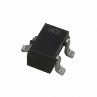
PDTC114TU,115 NXP Semiconductors, PDTC114TU,115 Datasheet - Page 5

PDTC114TU,115
Manufacturer Part Number
PDTC114TU,115
Description
TRANS PNP 50V 100MA SOT323
Manufacturer
NXP Semiconductors
Datasheet
1.PDTC114TT215.pdf
(11 pages)
Specifications of PDTC114TU,115
Configuration
Single
Transistor Polarity
NPN
Typical Input Resistor
10 KOhm
Mounting Style
SMD/SMT
Package / Case
SOT-323
Collector- Emitter Voltage Vceo Max
50 V
Peak Dc Collector Current
100 mA
Maximum Operating Temperature
+ 150 C
Minimum Operating Temperature
- 65 C
Lead Free Status / RoHS Status
Lead free / RoHS Compliant
Other names
934044080115::PDTC114TU T/R::PDTC114TU T/R
Philips Semiconductors
7. Characteristics
PDTC114T_SER_8
Product data sheet
Fig 1. DC current gain as a function of collector
(1) T
(2) T
(3) T
h
FE
600
400
200
0
10
V
current; typical values
amb
amb
amb
CE
1
= 5 V
= 150 C
= 25 C
= 40 C
1
Table 8:
T
(1)
(2)
(3)
Symbol
I
I
I
h
V
R1
C
CBO
CEO
EBO
amb
FE
CEsat
c
= 25 C unless otherwise specified.
Parameter
collector-base cut-off
current
collector-emitter
cut-off current
emitter-base cut-off
current
DC current gain
collector-emitter
saturation voltage
bias resistor 1 (input)
collector capacitance
10
Characteristics
I
C
006aaa552
(mA)
Rev. 08 — 9 February 2006
10
2
NPN resistor-equipped transistors; R1 = 10 k , R2 = open
Conditions
V
V
V
T
V
V
I
V
f = 1 MHz
C
j
CB
CE
CE
EB
CE
CB
= 150 C
= 10 mA; I
Fig 2. Collector-emitter saturation voltage as a
= 5 V; I
= 50 V; I
= 30 V; I
= 30 V; I
= 5 V; I
= 10 V; I
V
(1) T
(2) T
(3) T
CEsat
(V)
10
10
1
1
2
10
C
C
I
function of collector current; typical values
C
B
E
B
B
E
amb
amb
amb
= 0 A
/I
= 1 mA
1
B
= 0.5 mA
= 0 A
= 0 A
= 0 A;
= i
= 20
= 100 C
= 25 C
= 40 C
e
= 0 A;
PDTC114T series
1
(1)
(2)
(3)
© Koninklijke Philips Electronics N.V. 2006. All rights reserved.
Min
-
-
-
-
200
-
7
-
10
Typ
-
-
-
-
-
-
10
-
I
C
(mA)
006aaa553
Max
100
1
50
100
-
150
13
2.5
10
2
Unit
nA
nA
mV
k
pF
A
A
5 of 11


