SS5GL13 Omron, SS5GL13 Datasheet - Page 7
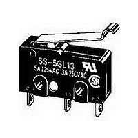
SS5GL13
Manufacturer Part Number
SS5GL13
Description
Manufacturer
Omron
Datasheet
1.SS5GL13.pdf
(8 pages)
Specifications of SS5GL13
Pole Throw Configuration
SPDT
Switch Function Configuration
N.O./N.C.
Actuator Style
Sim Roller Lever
Current Rating (max)
5A
Ac Voltage Rating (max)
250VVAC
Dc Voltage Rating (max)
14VVDC
Contact Material
Silver
Mechanical Life
30000000
Terminal Type
Solder
Product Height (mm)
21.9mm
Product Depth (mm)
6.4mm
Product Length (mm)
22.2mm
Operating Temp Range
-25C to 85C
Operating Force
0.49N
Lead Free Status / RoHS Status
Compliant


Precautions
Be sure to read the precautions and information common to all Snap Action and Detection Switches, contained in the Technical User’s Guide,
“Snap Action Switches, Technical Information” for correct use.
■ Correct Use
Mounting
Mount the switch onto a flat surface. Mounting on an uneven surface
may cause deformation of the switch, resulting in faulty operation or
breakage in the housing.
Operating Stroke
Take particular care in setting the operating stroke for the pin plunger
models. Make sure that the operating stroke is 70% to 100% of the
rated OT distance. Do not operate the actuator exceeding the OT dis-
tance, otherwise the life expectancy of the switch may be shortened.
Using Microloads
Using a model for ordinary loads to switch microloads may result in
faulty operation. Instead, use the models that are designed for
microloads and that operate in the following range;
However, even when using microload models within the operating
range shown above, if inrush current or inductive voltage spikes
occur when the contact is opened or closed, then contact wear may
increase and so decrease the service life. Therefore, insert a contact
protection circuit where necessary.
24
30
12
0
5
0.16mA
Inoperable
range
1mA
1
Operating range
for micro load
models SS-01
10
26mA
100mA 160mA
100mA
Current (mA)
100
Operating
range for
general-load
models
SS-5, SS-10
1,000
■ Cautions
Handling
Turn OFF the power supply before mounting or removing the switch,
wiring, or performing maintenance for inspection. Failure to do so
may result in electric shock or burning
Terminal Connection
When soldering the lead wire to the terminal, first insert the lead wire
conductor through the terminal hole and then solder.
Make sure that the capacity of the soldering iron is 60 W maximum.
Do not take more than 5 seconds to solder the switch terminal.
Improper soldering involving an excessively high temperature or
excessive soldering time may deteriorate the characteristics of the
switch.
Be sure to apply only the minimum required amount of flux. The
switch may have contact failures if flux intrudes in the interior of the
switch.
Use the following lead wires to connect to the solder terminals;
If the PCB terminal models are soldered in a solder bath, flux will per-
meate inside the switch and cause contact failure. Therefore, manu-
ally solder the PCB terminal.
Wire the quick-connect terminals (#110) with receptacles. Insert the
terminals straight into the receptacles. Do not impose excessive
force on the terminal in the horizontal direction, otherwise the termi-
nal may be deformed or the housing may be damaged.
Insulation Distance
Use a separator between the switch and metal mounting panels, to
ensure proper dielectric characteristics are achieved.
According to EN61058-1, the minimum insulation thickness for this
switch should be 1.1 mm and minimum clearance distance between
the terminal and mounting plate should be 1.6 mm. If the insulation
distance cannot be provided in the product incorporating the switch,
either use a switch with insulation barrier or use a separator to
ensure sufficient insulation distance.
Model
SS-10
SS-5
Snap Action Switch
Separator
Conductor size
0.5 to 0.75 mm
0.75 mm
SS
2
2
101
Related parts for SS5GL13
Image
Part Number
Description
Manufacturer
Datasheet
Request
R


Part Number:
Description:
SWITCH 5A BASIC PC MNT 150GF
Manufacturer:
Omron
Datasheet:

Part Number:
Description:
SWITCH BASIC SPDT .1A 150GF SLD
Manufacturer:
Omron
Datasheet:

Part Number:
Description:
SWITCH SPDT .1A SIM ROLLER SLD
Manufacturer:
Omron
Datasheet:

Part Number:
Description:
SWITCH SPDT 5A PIN PLUNGER SLD
Manufacturer:
Omron
Datasheet:

Part Number:
Description:
SWITCH SPDT 5A SIM ROLLER SLD
Manufacturer:
Omron
Datasheet:

Part Number:
Description:
SWITCH BASIC SPDT 5A
Manufacturer:
Omron
Datasheet:

Part Number:
Description:
SW BASIC SPDT 10.1A 150GF SLD
Manufacturer:
Omron
Datasheet:

Part Number:
Description:
SWITCH LEVER SPDT .1A
Manufacturer:
Omron
Datasheet:

Part Number:
Description:
SWITCH LEVER SPDT 5A
Manufacturer:
Omron
Datasheet:

Part Number:
Description:
SWITCH SIM ROLLER SPDT 5A
Manufacturer:
Omron
Datasheet:

Part Number:
Description:
SWITCH SPDT 10.1A HINGE RLLR SLD
Manufacturer:
Omron
Datasheet:

Part Number:
Description:
PIN PLUNGER SPDT 1.8OZ/5AMP
Manufacturer:
Omron
Datasheet:

Part Number:
Description:
SWITCH SPDT 5A PIN PLUNGER PCB
Manufacturer:
Omron
Datasheet:

Part Number:
Description:
SWITCH SPDT 5A HINGED ROLLER TAB
Manufacturer:
Omron
Datasheet: