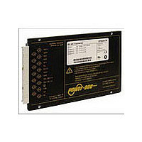
BP1101-9R POWER ONE, BP1101-9R Datasheet - Page 9

BP1101-9R
Manufacturer Part Number
BP1101-9R
Description
Manufacturer
POWER ONE
Type
Step Downr
Datasheet
1.BP1101-9R.pdf
(25 pages)
Specifications of BP1101-9R
Output Current
20A
Input Voltage
24V
Output Voltage
3.3V
Output Power
132
Screening Level
Commercial
Operating Temperature Min Deg. C
-40C
Operating Temperature Max Deg. C
71C
Product Length (mm)
164mm
Product Depth (mm)
111mm
Product Height (mm)
19.8mm
Mounting Style
Din-Rail
Pin Count
15
Number Of Outputs
1
Lead Free Status / RoHS Status
Not Compliant
BCD20010-G Rev AC, 26-Aug-09
Electrical Output Data
General Conditions:
– T
– Sense lines connected directly at the connector, inhibit (28) connected to Vi– (32).
– R input not connected
Table 5a: Output data for single-output powertrains
Table 5b: Output data for single-output powertrains. General conditions as in table 5a
Output
Characteristics
V
V
V
I
I
I
v
v
t
V
Output
Characteristics
V
V
V
I
I
I
v
v
t
V
1
2
3
4
5
o max
o nom
oL
d
o nom
o max
oL
d
o
o d
o
ow
o d
o
o tr
o P
o
ow
o tr
5
o P
5
A
If the output voltages are increased above V
accordingly, so that P
Breakdown voltage of the incorporated suppressor diode at 10 mA (3.3 V, 5.1 V) or 1 mA (12 V). Exceeding this voltage might
damage the suppressor diode.
See Output Power at Reduced Temperature
Measured according to IEC/EN 61204 with a probe described in annex A
Recovery time until V
= 25°C, unless T
Output voltage
Worstcase output
voltage
Overvoltage protection
Nominal output current
Max. output current
Output current limit
Output
noise
Dynamic
load
regulation
Output voltage trim
range (via R input)
Output voltage
Worstcase output
voltage
Overvoltage protection
Nominal output current
Max. output current
Output current limit
Output
noise
Dynamic
load
regulation
Output voltage trim
range (via R input)
4
4
Switch. frequ.
Total incl. spikes BW = 20 MHz
Switch. frequ.
Total incl. spikes BW = 20 MHz
Voltage
deviation
Recovery time
Voltage
deviation
Recovery time
Single-output powertrain
Single-output powertrain
1
1
C
o max
®
o
is specified.
returns to ±1% of V
3
3
and T
2
2
Conditions
V
V
T
I
V
T
V
V
I
1.1 V
(0.1 – 1) I
T
Conditions
V
V
T
I
V
T
V
V
I
1.1 V
(0.1 – 1) I
T
C max
o
o max
o
o max
C min
C min
C min
i nom
i min
i min
i nom
i nom
C min
C min
C min
i nom
i min
i min
i nom
i nom
= 0 – I
= 0 – I
, I
↔
i min
, I
– V
– V
, I
, I
↔
i min
– V
– V
are not exceeded.
– T
– T
– T
– T
– T
– T
o nom
o max
o nom
o max
o max
1
o max
1
i max
i max
/
i max
i max
/
C max
C max
– V
C max
2
o max
C max
C max
– V
C max
2
o max
I
I
o max
o max
o
i max
; see Dynamic Load Regulation.
i max
o nom
through R-input control or remote sensing, the output power should be reduced
14.93
14.78
min
3.28
3.24
6.45
20.5
1.79
min
17.1
6.8
8.1
Page 9 of 25
3.3 V
15 V
typ
typ
6.5
7.2
1.2
0.2
3.3
6.8
0.7
0.4
15
18
15
40
15
20
22
20
4
5
15.08 23.88
15.23 23.64
max
3.32
max
3.35
3.63
18.9
16.5
25
8.2
min
5.07
5.02
6.45
18.9
2.75
min
28.5
4.2
13
90 – 194 Watt DC-DC Converters
5.1 V
19.8
typ
5.1
6.8
0.8
0.3
0.15
12
20
18
typ
24 V
2.5
4.4
0.5
5
24
30
15
50
4
max
5.13
5.18
22.5
5.61
24.12
24.36
max
31.5
26.4
5.0
P Series Data Sheet
11.94
11.82
min
14.3
8.4
6.5
Unit
mV
ms
V
A
V
V
pp
12 V
0.15
typ
8.8
1.2
15
12
15
30
www.power-one.com
5
8
12.06
12.18
max
15.8
10.0
13.2
mV
Unit
ms
V
A
V
V
pp


