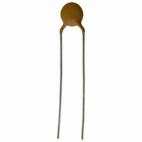
PTCCL07H321DTE Vishay, PTCCL07H321DTE Datasheet - Page 2

PTCCL07H321DTE
Manufacturer Part Number
PTCCL07H321DTE
Description
PTC CP LDD 7D00 A320 030 140 T E3
Manufacturer
Vishay
Series
661r
Type
PTCr
Specifications of PTCCL07H321DTE
Voltage - Max
30V
Current - Hold (ih) (max)
320mA
Current - Trip (it)
480mA
Current - Max
3.5A
Package / Case
Radial
Mounting Style
Through Hole
Pin Count
2
Screening Level
Industrial
Resistance @ 25c
5Ohm
Percentage Of Resistance Tolerance @ 25c
±20
Operating Temperature Min Deg. C
-40C
Operating Temperature Max Deg. C
85C
Product Length (mm)
Not Requiredmm
Product Height (mm)
Not Requiredmm
Product Depth (mm)
4mm
Lead Free Status / RoHS Status
Lead free / RoHS Compliant
R Min/max
-
Time To Trip
-
Lead Free Status / RoHS Status
Lead free / RoHS Compliant
Other names
2322 661 53211
232266153211
BC1338
PTCCL07H321DBC
232266153211
BC1338
PTCCL07H321DBC
BCcomponents
FEATURES
MARKING
2000 Oct 13
Different voltages to be chosen in
function of the application
Available in three mechanical
versions:F
– 2322 66. 4.... naked discs
– 2322 66. 5.... leaded and coated
– 2322 66. 6.... taped, on reel
Wide range of trip and non-trip
currents: from 17 mA up to 3 A for
the trip current
Wide range of resistance: from
0.3
Small ratio between trip and
non-trip currents
(I
High maximum inrush current
Excellent long term behaviour, also
in humidity
Leaded parts withstand mechanical
stresses and vibration
UL approved PTCs are guaranteed to
withstand severe test programmes
including:
– long-life cycle tests
– long-life storage tests
– electrical cycle tests at low
– damp-heat and water immersion
– overvoltage tests at up to 200% of
UL file E148885 according to
XGPU2 standard UL1434.
Clear marking: the grey lacquered
thermistors with a diameter of 8.5 to
20 mm are marked with BC,
R
and I
PTC thermistors for
overload protection
t
25
/I
(to diameter 12.5 mm)
(over 5000 trip cycles)
(3000 hours at 250 C)
ambient temperatures ( 40 C or
0 C)
tests
rated voltage.
nt
value (example 4R6) on one side
nt
= 1.5 at 25 C)
up to 3 k
, V
max
on the other.
APPLICATIONS
QUICK REFERENCE DATA
Notes
1. 2322 660 4/5/6 ...3 types, have a 120 C switch temperature.
2. Rated voltages are respectively:
Switch temperature; note 1
Maximum voltage; note 2:
Temperature range:
Climatic category:
Telecommunications
Automotive systems
Industrial electronics
Consumer electronics
Electronic data processing.
2322 66. 4/5/6...1
2322 66. 4/5/6...2
2322 66. 4/5/6...3
2322 66. 4/5/6...1
2322 66. 4/5/6...2
2322 66. 4/5/6...3
66. 4/5/6...1
66. 4/5/6...2/3
24 to 48 V (AC or DC)
120 V (AC or DC)
230 V (AC or DC).
PARAMETER
2
30 to 60 V, 145 V and
265 V (T
DESCRIPTION
These directly heated thermistors have
a positive temperature coefficient and
are primarily intended for overload
protection. They consist of a naked
disc or with two tinned brass or copper
clad steel leads and coated.
30 to 60
145
265
0 to 70
0 to 70
40/125/56
25/125/56
140
40 to +85
VALUE
s
Product specification
= 140 C)
V (DC)
V (RMS)
V (RMS)
C
C
C
C
UNIT


