PTCCL07H321DTE Vishay, PTCCL07H321DTE Datasheet
PTCCL07H321DTE
Specifications of PTCCL07H321DTE
232266153211
BC1338
PTCCL07H321DBC


Related parts for PTCCL07H321DTE

PTCCL07H321DTE Summary of contents
Page 1
DATA SHEET 145 V and 265 140 C) s PTC thermistors for overload protection Product specification Supersedes data of 17th May 1999 File under BCcomponents, BC02 BCcomponents 2000 Oct 13 ...
Page 2
BCcomponents PTC thermistors for overload protection FEATURES Different voltages to be chosen in function of the application Available in three mechanical versions:F – 2322 66. 4.... naked discs – 2322 66. 5.... leaded and coated – 2322 66. 6.... taped, ...
Page 3
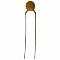
BCcomponents PTC thermistors for overload protection MECHANICAL DATA Dimensions in mm. For D see Table 1; for T and T see Table 2. 1 Fig.1 Component outline for 2322 66. 4/5...1/2/3. 2000 Oct ...
Page 4
BCcomponents PTC thermistors for overload protection Table 1 Device and tape dimensions, packaging and catalogue numbers MAX. MAX. MAX. (mm) (mm) (mm 9 11.5 8.5 29.5 13.0 10.5 31.5 15.0 12.5 ...
Page 5
ELECTRICAL DATA AND ORDERING INFORMATION Table 3 Electrical data and ordering information for 2322 66. 4/5/6...1; max. voltage = (AC or DC); see note 1. Preferred types in shaded cells. (2) ( ...
Page 6
Table 4 Electrical data and ordering information for 2322 66. 4/5/6...2; max. voltage = 145 V (AC or DC); see note 1 (2) ( MAX. MIN. 25 ...
Page 7
Table 5 Electrical data and ordering information for 2322 66. 4/5/6...3; max. voltage = 265 V (AC or DC); see note 1. Preferred types in shaded cells. (2) ( MAX. MIN. 25 ...
Page 8
BCcomponents PTC thermistors for overload protection 250 % 200 I t 150 I nt 100 I max Fig.2 Current deviation as a function of the ambient temperature. 2000 Oct 145 V ...
Page 9
BCcomponents PTC thermistors for overload protection 200 I max (%) 150 100 stated in Tables 3, 4 and 5 is the maximum overload current that may flow through the PTC when passing from the max low ...
Page 10
BCcomponents PTC thermistors for overload protection Curve 1: typical mm. Curve 2: typical mm. Curve 3: typical D = 12.0 mm. Curve 4: ...
Page 11
BCcomponents PTC thermistors for overload protection Curve 1: typical D = 20.0 mm. Curve 2: typical D = 16.0 mm. Curve 3: typical D = 12.0 mm. ...
Page 12
BCcomponents PTC thermistors for overload protection Typical R/T characteristics 59491 51311 100 150 Fig.6 Typical resistance/temperature characteristic for 2322 660 59491/51311 ...
Page 13
BCcomponents PTC thermistors for overload protection 59211 51211 1 51321 100 150 Fig.10 Typical resistance/temperature characteristic for 2322 662 59211 and 663 51121/51321 ...
Page 14
BCcomponents PTC thermistors for overload protection 52112 10 52512 52712 100 150 Fig.14 Typical resistance/temperature characteristic for 2322 661 52112/52512/52712 ...
Page 15
BCcomponents PTC thermistors for overload protection 100 150 Fig.18 Typical resistance/temperature characteristic for 2322 660 51193/51593/51993 ...
Page 16
BCcomponents PTC thermistors for overload protection 52113 52513 2 10 52813 100 150 Fig.22 Typical resistance/temperature characteristic for 2322 662 52113/52513/52813 ...
Page 17
BCcomponents PTC thermistors for overload protection PACKAGING Tape and reel specifications All tape and reel specifications are in accordance with “IEC 60286-3”. Basic dimensions are given in Figs 25 and 26, and Tables 6 and 7. Tape dimensions d L ...
Page 18
BCcomponents PTC thermistors for overload protection Table 6 Tape and other device dimensions; see Figs 1 and 25 SYMBOL PARAMETER D body diameter T total maximum thickness d lead diameter P pitch between thermistors feed ...
Page 19
BCcomponents PTC thermistors for overload protection Reel specifications Dimensions in mm. For W and W , see Table Fig.26 Dimensions of the reel for 2322 66. 6...1/2/3. Table 7 Reel dimensions; see Fig.26 DIAMETER (mm) <12 12 ...
Page 20
BCcomponents PTC thermistors for overload protection PACKAGING INFORMATION PACKAGING SPQ 5000 3000 500 3000 6000 3000 3000 250 3000 5500 3000 250 3000 250 1500 200 3000 200 1500 200 3000 200 1500 400 200 100 400 100 50 2000 ...
Page 21
BCcomponents PTC thermistors for overload protection TESTS AND REQUIREMENTS Clause numbers of tests and performance requirements refer to the CECC 44000 standard. Inspection levels are selected from “IEC 60410”. Tables with requirements for lot-by-lot and periodic tests. In these tables: ...
Page 22
BCcomponents PTC thermistors for overload protection CLAUSE TEST NUMBER GROUP 4.12 robustness of terminations 4.13.2 resistance to soldering heat 4.14 rapid change of temperature GROUP 4.20.3 endurance at maximum rated temperature and ...