MOD-GSM-EDGE Olimex Ltd., MOD-GSM-EDGE Datasheet - Page 13
MOD-GSM-EDGE
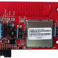
Manufacturer Part Number
MOD-GSM-EDGE
Description
RF Modules & Development Tools EDGE WIRELESS PROTOTYPE MODULE
Manufacturer
Olimex Ltd.
Datasheet
1.MOD-GSM-EDGE.pdf
(18 pages)
Specifications of MOD-GSM-EDGE
Board Size
43.5 mm x 26 mm x 2.9 mm
Product
RF Development Tools
Maximum Frequency
1900 MHz
Output Power
800 mA
Antenna
External
Supply Voltage (max)
4.5 V
Maximum Operating Temperature
+ 60 C
Lead Free Status / RoHS Status
Lead free / RoHS Compliant


5V_CHG_E
DCDC_E
Download
MTX/DTX
MRX/DRX
AGND_E
USB_PWR_E
Default state closed
This jumper is used when the battery is present and allows battery charging.
Connects the DCDC converter output (5V or 4V according 4V_E jumper state) to
VCHG power pin of SIM700D module.
Enable DCDC. Connect DCDC output (5V or 4V according 4V_E jumper state) to the
module.
When the jumper is closed SIM700D firmware upgrade is allowed.
The MainTX/DebugTX defines whether Main TX terminal or Debug TX terminal of
SIM700D module is connected to FT232RL virtual com port driver.
The MainRX/DebugRX define whether Main RX terminal or Debug RX terminal of
SIM700D module is connected to FT232RL virtual com port driver.
Enable USB +5 V power supply.
Default state is closed
Default state closed
Default state – open
Default state is DTX
Default state is DRX
Enable board analog ground.
Default state is closed
Important: 4V_E, 4V and 5V_CHG_E jumpers have to be moved together.
Do not plug in external +12V if BAT_E jumper is open!
Page 13
Related parts for MOD-GSM-EDGE
Image
Part Number
Description
Manufacturer
Datasheet
Request
R

Part Number:
Description:
RF Modules & Development Tools GSM WIRELESS PROTOTYPE MODULE
Manufacturer:
Olimex Ltd.
Datasheet:
Part Number:
Description:
RF Modules & Development Tools GSM-B WIRELESS PROTOTYPE MODULE
Manufacturer:
Olimex Ltd.
Datasheet:

Part Number:
Description:
MCU, MPU & DSP Development Tools GPS SIRF STAR III MOD 20-CH 38mA 4G
Manufacturer:
Olimex Ltd.
Datasheet:

Part Number:
Description:
MOD USB-MCU FT245RL W/18LF8722
Manufacturer:
DLP Design Inc
Datasheet:

Part Number:
Description:
MOD OEM WIRELESS LAN 311G I
Manufacturer:
ConnectBlue
Datasheet:

Part Number:
Description:
MOD OEM WIRELESS LAN 311G I
Manufacturer:
ConnectBlue
Datasheet:

Part Number:
Description:
MOD OEM WIRELESS LAN 211G I
Manufacturer:
ConnectBlue
Datasheet:
Part Number:
Description:
MOD OEM WIRELESS LAN 211G X
Manufacturer:
ConnectBlue
Datasheet:

Part Number:
Description:
MOD SZ8 COAX SOCK CONT-RG142
Manufacturer:
TE Connectivity
Datasheet:


Part Number:
Description:
Microcontroller & Microprocessor Development Tools MP3 PLYR MOD WITH VS1002
Manufacturer:
Olimex Ltd.
Datasheet:
Part Number:
Description:
Microcontroller & Microprocessor Development Tools MP3 PLYR MOD BAT WITH VS1002
Manufacturer:
Olimex Ltd.
Datasheet:

Part Number:
Description:
Microcontroller & Microprocessor Development Tools TCP-IP DEV BRD PIC32MX460F512
Manufacturer:
Olimex Ltd.
Datasheet:

Part Number:
Description:
Microcontroller & Microprocessor Development Tools PROTOTYPE BOARD TMS320F28027
Manufacturer:
Olimex Ltd.
Datasheet:

Part Number:
Description:
Microcontroller & Microprocessor Development Tools HDR BRD FOR LPC3131
Manufacturer:
Olimex Ltd.
Datasheet: