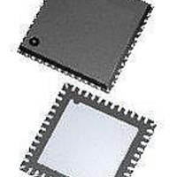
ATA5279-PLQW Atmel, ATA5279-PLQW Datasheet - Page 36

ATA5279-PLQW
Manufacturer Part Number
ATA5279-PLQW
Description
RF Wireless Misc High-end multiple antenna driver IC
Manufacturer
Atmel
Datasheet
1.ATA5279P-PLQW.pdf
(40 pages)
Specifications of ATA5279-PLQW
Package / Case
VQFN-48
Mounting Style
SMD/SMT
Lead Free Status / RoHS Status
Lead free / RoHS Compliant
8. Functional Parameters (Continued)
All parameters valid for 7.0V VS 16.5V and –40°C T
36
*) Type means: A = 100% tested, B = 100% correlation tested, C = Characterized on samples, D = Design parameter
Notes:
10.15 Current step 15 level
10.16 Current step 16 level
10.17 Current step 17 level
10.18 Current step 18 level
10.19 Current step 19 level
10.20 Current step 20 level
11.10
11.11
11.12
11.13
11.14 Output sink capability
11.15 Input current
11.1
11.2
11.3
11.4
11.5
11.6
11.7
11.8
11.9
No.
11
1. In this column, pin group names are given. Please refer to
2. Operation of coils with higher impedance than the given value is possible but functional limitations might occur (inability to
Parameters
Digital Interface (SPI, Control Logic)
Supply current in
operation mode
Supply current in
power-down mode
SPI clock low-phase
timing
SPI clock high-phase
timing
SPI output enabling
time
SPI output disabling
time
Minimum SPI disable
time
Minimum chip select
setup time
Minimum chip select
hold time
Minimum data input
setup time
Minimum data input
hold time
Output source
capability
SPI clock period
Atmel ATA5279
more details.
reach to configured coil current). Coils with lower impedance should not be used as they might be detected as faulty.
Test Conditions
V
V
Chip in operation
Chip in operation
Chip in operation
Chip in operation
Chip in operation
Chip in operation
Chip in operation
Chip in operation
Chip in operation
Chip in operation
V
I
V
I
V
V
V
V
Source
sink
VIF
VIF
VIF
VIF
in
VIF
in
VIF
= 0V
= 5.5V
= 1mA
= 5.0V
= 5V
= 5 V
= 5.5V
= 5.5V
5.5V
= –1mA
a
105°C unless otherwise noted.
Pin
DO
DO
39
39
39
37
38
39
40
37
38
39
40
6
6
-
-
-
-
-
-
t
t
MISOon,max
MISOoff,max
t
Symbol
V
V
V
V
V
V
t
t
CShold,min
t
Section 2. “Pin Configuration” on page 2
SPIoff,min
CSset,min
t
setup,min
I
t
hold,min
V
t
V
REF,S15
REF,S16
REF,S17
REF,S18
REF,S19
REF,S20
supVIF
T
Lo,min
hi,min
I
I
dig,H
in,H
dig,L
in,L
SPI
4
1/f
1/f
1/f
1/f
1/f
Min.
4.75
–0.2
–0.2
–0.2
735
784
833
882
931
980
100
100
–60
2
2
4
2
2
0.6
12
1/f
OSCI
OSCI
OSCI
OSCI
OSCI
0
0
0
OSCI
Typ.
1.9
2
Max.
1020
0.25
765
816
867
918
969
100
100
–20
0.2
0.2
0.2
30
40
3
0
0
0
in this document for
Unit
mV
mV
mV
mV
mV
mV
mA
µA
µA
ns
ns
ns
ns
V
V
s
s
s
s
s
s
9125L–RKE–03/11
Type*
D
D
D
D
D
D
D
D
D
D
A
A
A
A
A
A
A
A
A
A
A


