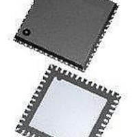
ATA5279-PLQW Atmel, ATA5279-PLQW Datasheet - Page 15

ATA5279-PLQW
Manufacturer Part Number
ATA5279-PLQW
Description
RF Wireless Misc High-end multiple antenna driver IC
Manufacturer
Atmel
Datasheet
1.ATA5279P-PLQW.pdf
(40 pages)
Specifications of ATA5279-PLQW
Package / Case
VQFN-48
Mounting Style
SMD/SMT
Lead Free Status / RoHS Status
Lead free / RoHS Compliant
Figure 3-9.
3.7.1
Figure 3-10. Timing Parameters of the SPI Communication
9125L–RKE–03/11
S_CLK
S_CS
MISO
MOSI
Timing
S_CLK
SPI Operation in POL = 0 and PHA = 1 Mode
S_CS
MISO
MOSI
Z
X X
X
X
Z
X
Setup
The configuration mode can be selected with the appropriate SPI command (see
“General Command Description” on page
always in its default configuration (POL = 1, PHA = 1), which must be used to alter the config-
uration. At the end of the SPI configuration-changing command, the new configuration is
activated with the falling edge of the S_CS signal.
Figure 3-10
Note:
t
CS,set
t
setup
Sample
LSB
LSB
The diagram above is using POL = 0 and PHA = 0 as a setup for the SPI. The values are also
valid for the other three configurations. The limits for the timing values shown above can be
found in
t
t
hold
hi
t
illustrates the timing parameters of the SPI communication.
SPI
t
Io
Section 8. “Functional Parameters” on page
1
1
2
t
out,valid
6
3
21). Note that after power-up or a reset, the IC is
MSB
4
t
MISOoff
t
CShold
X
X
32.
5
t
SPIoff
Atmel ATA5279
X
X
6
t
MISOon
MSB
Section 3.9.2
Z
X
15


