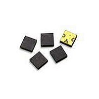
ACMD-7402-BLK Avago Technologies US Inc., ACMD-7402-BLK Datasheet - Page 2

ACMD-7402-BLK
Manufacturer Part Number
ACMD-7402-BLK
Description
RF Transceiver FBAR Duplexer
Manufacturer
Avago Technologies US Inc.
Series
-r
Datasheet
1.ACMD-7402-TR1.pdf
(10 pages)
Specifications of ACMD-7402-BLK
Frequency Bands (low / High)
1.85GHz ~ 1.9GHz / 1.93GHz ~ 1.99GHz
Low Band Attenuation (min / Max Db)
52.00dB / -
High Band Attenuation (min / Max Db)
43.00dB / -
Return Loss (low Band / High Band)
20dB / 17dB
Mounting Type
Surface Mount
Package / Case
3-CSP
Pin Count
3
Screening Level
Commercial
Package Type
CSP
Lead Free Status / RoHS Status
Lead free / RoHS Compliant
ACMD-7402 Electrical Specifications, Z
Symbol
Antenna Port to Receive Port
S23
S22
S23
S23
S23
Transmit Port to Antenna Port
S31
S11
S31
S31
S31
Antenna Port
S33
S33
Isolation Transmit Port to Receive Port
S21
S21
Notes:
1. T
2. Min/Max specifications are guaranteed at the indicated temperature with the input power to the Tx ports equal to or less than +29 dBm
3. Typical data is the average value of the parameter over the indicated band at the specified temperature. Typical values may vary over time.
4. At Tx input power between +26 dBm and +29 dBm, the Insertion Loss at the upper edge of the Tx band (1907– 1909.5 MHz) will be slightly
2
S23
S31
board.
over all Tx frequencies unless otherwise noted.
Refer to “Characterization” section for measurement details.
degraded. From 1907 to 1909.5 MHz, the maximum Insertion Loss specification at Tc = +85 C is guaranteed to +26 dBm input power.
C
is the case temperature and is defined as the temperature of the underside of the Duplexer where it makes contact with the circuit
Insertion Loss in Receive Band
Return Loss of Receive Port
Attenuation in Transmit Band
Attenuation 0 – 1600 MHz
Attenuation in Receive 2
Insertion Loss in Transmit Band
Return Loss of Transmit Port
Attenuation in Receive Band
Attenuation 0 – 1600 MHz
Attenuation in Transmit 2
Return Loss of Antenna Port in
Return Loss of Antenna Port in
Tx-Rx Isolation in Receive Band
Tx-Rx Isolation in Transmit Band
Parameter
(1930.5 – 1989.5 MHz)
Ripple (p-p) in Receive Band
in Receive Band
(1850.5 – 1909.5 MHz)
Harmonic Band
(3861 – 3979 MHz)
(1850.5 – 1909.5 MHz)
Ripple (p-p) in Transmit Band
in Transmit Band
(1930.5 – 1989.5 MHz)
Harmonic Band
(3701 – 3819 MHz)
Receive Band
(1930.5 – 1989.5 MHz)
Transmit Band
(1850.5 – 1909.5 MHz)
(1930.5 – 1989.5 MHz)
(1850.5 – 1909.5 MHz)
nd
0
nd
= 50 , T
Units
dB
dB
dB
dB
dB
dB
dB
dB
dB
dB
dB
dB
dB
dB
dB
dB
C
[1,2]
as indicated
Min Typ
9.5
9.5
45
54
52
43
9
9
– 30 C
[3]
[2]
Max Min Typ
3.8
3.0
3.0
2.3
9.5
9.5
52
20
18
43
22
45
54
8
9
9
+25 C
1.5
1.5
1.1
0.9
17
56
31
19
20
48
34
13
16
19
48
58
[3]
[2]
Max Min Typ
3.5
2.6
3.0
2.3
9.5
9.5
52
43
45
54
9
9
+85 C
[3]
[2]
3.5
Max
3.5
2.6
2.8
[4]


