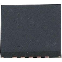
ATA5276M-PGPW19 Atmel, ATA5276M-PGPW19 Datasheet - Page 6

ATA5276M-PGPW19
Manufacturer Part Number
ATA5276M-PGPW19
Description
RF Wireless Misc 125KHz, Antenna Driver IC
Manufacturer
Atmel
Type
Transmitter ICr
Datasheet
1.ATA5276M-PGQW.pdf
(18 pages)
Specifications of ATA5276M-PGPW19
Operating Frequency
125 KHz
Supply Voltage (max)
24 V
Supply Voltage (min)
8 V
Supply Current
10 mA
Operating Temperature Range
- 40 C to + 105 C
Package / Case
QFN-20
Mounting Style
SMD/SMT
Lead Free Status / RoHS Status
Lead free / RoHS Compliant
Available stocks
Company
Part Number
Manufacturer
Quantity
Price
Company:
Part Number:
ATA5276M-PGPW19
Manufacturer:
TI
Quantity:
1 001
4.3.3
4.3.4
6
ATA5276
Time Out and Time Out Reset
Transmission Acknowledge and Error Signal
The IC has a time out supervisor for the interface line to avoid unintended continuous transmis-
sion in case of line errors. The time out timer runs if the DIO pin is pulled to a low level. If the DIO
pin is permanently low for more than the time T
the standby mode. This avoids the discharging of the supply battery if the DIO line has a failure
like a body contact or another permanent low level failure. The time T
antenna resonance frequency.
Figure 4-6.
For continuous transmission periods the internal time out timer must be reset within the time out
reset period T
can be made by cyclical resetting of the time out timer (see
depends on the antenna resonance frequency.
If no failure is detected during a transmission sequence the IC acknowledges the transmission
by pulling the DIO line to low level for time T
generated at the end of a transmission sequence if the DIO line was high for the time T
ically 16 ms).
Their are two types of error detection (see section
At the end of transmission the IC indicates the failure by an error signal by pulling the DIO line to
a low level for time T
With the acknowledge and the error signal a connected microcontroller is able to recognize fail-
ures of the IC or the antenna module as well as DIO line failures like a broken wire or a short
circuit.
• Immediate switch-off of the driver stage
• The failure is indicated through the DIO line based on transmission acknowledge and Error
signal
DIO
DRV
Standby
ORP
Time Out and Time Out Reset Protocol
with a short high pulse of length T
Transmission
Delay
ERR
TD_L TOUT_L
(typically 128 µs) instead of T
Time Out
Standby
Timeout
Reset
ACK
TOR
OUTL
(typically 256 µs). The acknowledge signal is
“Diagnosis and Protection” on page
Reset Periode
the driver is switched off and the IC enters
TORP
Time Out
OR
ACK
at DIO. Any transmission time periods
.
Figure
4-6). The time T
TD_H
OUTL
Transmission
Delay
depends on the
4909C–AUTO–01/07
ORP
OUTH
8):
and T
(typ-
OR


