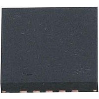
ATA5276M-PGPW19 Atmel, ATA5276M-PGPW19 Datasheet - Page 4

ATA5276M-PGPW19
Manufacturer Part Number
ATA5276M-PGPW19
Description
RF Wireless Misc 125KHz, Antenna Driver IC
Manufacturer
Atmel
Type
Transmitter ICr
Datasheet
1.ATA5276M-PGQW.pdf
(18 pages)
Specifications of ATA5276M-PGPW19
Operating Frequency
125 KHz
Supply Voltage (max)
24 V
Supply Voltage (min)
8 V
Supply Current
10 mA
Operating Temperature Range
- 40 C to + 105 C
Package / Case
QFN-20
Mounting Style
SMD/SMT
Lead Free Status / RoHS Status
Lead free / RoHS Compliant
Available stocks
Company
Part Number
Manufacturer
Quantity
Price
Company:
Part Number:
ATA5276M-PGPW19
Manufacturer:
TI
Quantity:
1 001
4. Functional Description
4.1
4.2
4
Operation Modes
Standby Mode and Wake-up
ATA5276
There are two different operation modes for the ATA5276:
After power-on-reset, the ATA5276 is in standby mode. For minimum power consumption, only
the internal 5V supply and the DIO line interface are active. The IC can be activated by the exter-
nal control unit via the serial interface. The DIO line is called logic high if it is pulled up to the
VDIO voltage level. The DIO line is called logic low if it is pulled down to the VSS voltage level. A
low signal at the DIO line wakes-up the IC.
The circuit enters the standby mode if either of these three conditions are fulfilled:
Notes:
Figure 4-1.
Figure 4-2.
• Standby mode
• Transmission mode
1. After power-on-reset and the DIO is high (see
2. After a time out of T
3. After a time out of T
page
time T
1. Time does not depend on the antenna resonance frequency.
2. Time depends on the antenna resonance frequency.
5)
ACK
STBY After POR
STBY After DIO = H
/T
ERR
(1)
(see
OUTL
OUTH
Figure
(1)
(2)
during which DIO is permanently low (see
during which DIO is permanently high and an acknowledge
4-2)
POR
STBY
DIO
STBY
DIO
TOUT_H
Figure
TACK/TERR
t
t
t
t
t
4-1)
Figure 4-3 on
4909C–AUTO–01/07


