ST13005 STMicroelectronics, ST13005 Datasheet
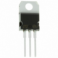
TRANSISTOR NPN 400V 4A TO-220

ST13005

Manufacturer Part Number
ST13005
Description
TRANSISTOR NPN 400V 4A TO-220
Manufacturer
STMicroelectronics
Datasheets

Specifications of ST13005

Transistor Type
NPN
Current - Collector (ic) (max)
4A
Voltage - Collector Emitter Breakdown (max)
400V
Vce Saturation (max) @ Ib, Ic
1V @ 1A, 4A
Current - Collector Cutoff (max)
1mA
Dc Current Gain (hfe) (min) @ Ic, Vce
8 @ 2A, 5V
Power - Max
75W
Mounting Type
Through Hole
Package / Case
TO-220-3 (Straight Leads)
Transistor Polarity
NPN
Collector Emitter Voltage V(br)ceo
400V
Power Dissipation Pd
75W
Dc Collector Current
4A
Dc Current Gain Hfe
15
Transistor Case Style
TO-220
No. Of Pins
3
Svhc
No SVHC
Rohs Compliant
Yes
Lead Free Status / RoHS Status
Contains lead / RoHS non-compliant
Frequency - Transition
-
Other names
497-3149-5

Available stocks

Company
Part Number
Manufacturer
Quantity
Price
Part Number:
ST13005
Manufacturer:
STM
Quantity:
7 500
Part Number:
ST13005
Manufacturer:
LT
Quantity:
1 500
Part Number:
ST13005
Manufacturer:
ST
0
Part Number:
ST13005
Manufacturer:
ST
Quantity:
20 000
Company:
Part Number:
ST13005
Quantity:
33 000
Company:
Part Number:
ST13005
Quantity:
33 000
Part Number:
ST13005 ( D )
Manufacturer:
ST
0
Part Number:
ST13005(A)
Manufacturer:
ST
0
Part Number:
ST13005,A,ST13009L
Manufacturer:
ST
0
Part Number:
ST13005,ST13009L,ST13009,ST13007A,A,
Manufacturer:
ST
0
Part Number:
ST13005A
Manufacturer:
ST
Quantity:
219
Part Number:
ST13005A
Manufacturer:
ST
Quantity:
222
Part Number:
ST13005A
Manufacturer:
ST
Quantity:
20 000
Company:
Part Number:
ST13005A
Quantity:
100 000
APPLICATIONS:
DESCRIPTION
The devices are manufactured using high voltage
Multi
switching speeds and medium voltage capability.
They use a Cellular Emitter structure with planar
edge termination to enhance switching speeds
while maintaining the wide RBSOA.
ABSOLUTE MAXIMUM RATINGS
June 2001
Symbol
MEDIUM VOLTAGE CAPABILITY
NPN TRANSISTORS
LOW SPREAD OF DYNAMIC PARAMETERS
MINIMUM LOT-TO-LOT SPREAD FOR
RELIABLE OPERATION
VERY HIGH SWITCHING SPEED
THROUGH-HOLE I2PAK (TO-262) POWER
PACKAGE IN TUBE (SUFFIX ”-1”)
ELECTRONIC BALLASTS FOR
FLUORESCENT LIGHTING
SWITCH MODE POWER SUPPLIES
V
V
V
T
P
I
I
CEO
CES
EBO
I
CM
T
I
BM
stg
C
B
tot
j
Epitaxial Planar
Collector-Emitter Voltage (V
Collector-Emitter Voltage (I
Emitter-Base Voltage (I
Collector Current
Collector Peak Current (t
Base Current
Base Peak Current (t
Total Dissipation at T
Storage Temperature
Max. Operating Junction Temperature
®
technology for
Parameter
p
c
< 5 ms)
= 25
C
p
= 0)
< 5 ms)
B
o
BE
C
= 0)
HIGH VOLTAGE FAST-SWITCHING
= 0)
high
NPN POWER TRANSISTORS
INTERNAL SCHEMATIC DIAGRAM
TO-220
-65 to 150
1
Value
2
700
400
150
75
3
9
4
8
2
4
STB13005-1
ST13005
(Suffix "-1")
TO-262
I2PAK
1 2
Unit
3
o
o
W
V
V
V
A
A
A
A
C
C
1/8

Related parts for ST13005

ST13005 Summary of contents

Page 1

... Total Dissipation at T tot T Storage Temperature stg T Max. Operating Junction Temperature j June 2001 HIGH VOLTAGE FAST-SWITCHING NPN POWER TRANSISTORS high INTERNAL SCHEMATIC DIAGRAM = < 5 ms) p < ST13005 STB13005 TO-220 I2PAK TO-262 (Suffix "-1") Value 700 400 -65 to 150 150 3 Unit ...

Page 2

... ST13005 / STB13005-1 THERMAL DATA R Thermal Resistance Junction-case thj-case ELECTRICAL CHARACTERISTICS (T Symbol Parameter I Collector Cut-off CEV Current (V = -1.5V Emitter Cut-off EBO Current ( Collector-Emitter CEO(sus) Sustaining Voltage ( Collector-Emitter CE(sat) Saturation Voltage V Base-Emitter BE(sat) Saturation Voltage h DC Current Gain FE RESISTIVE LOAD t Storage Time s t Fall Time f Pulsed: Pulse duration = 300 s, duty cycle = 1 ...

Page 3

... Safe Operating Areas DC Current Gain Collector Emitter Saturation Voltage ST13005 / STB13005-1 Derating Curve DC Current Gain Base Emitter Saturation Voltage 3/8 ...

Page 4

... ST13005 / STB13005-1 Inductive Fall Time Resistive Fall Time Reverse Biased SOA 4/8 Inductive Storage Time Resistive Load Storage Time ...

Page 5

... Figure 1: Inductive Load Switching Test Circuit. 1) Fast electronic switch 2) Non-inductive Resistor 3) Fast recovery rectifier Figure 2: Resistive Load Switching Test Circuit. 1) Fast electronic switch 2) Non-inductive Resistor ST13005 / STB13005-1 5/8 ...

Page 6

... ST13005 / STB13005-1 DIM. MIN. A 4.40 C 1.23 D 2.40 E 0.49 F 0.61 F1 1.14 F2 1.14 G 4.95 G1 2.40 H2 10. 13.00 L5 2.65 L6 15.25 L7 6.20 L9 3.50 M DIA. 3.75 6/8 TO-220 MECHANICAL DATA mm TYP. MAX. 4.60 1.32 2.72 0.70 0.88 1.70 1.70 5.15 2.70 10.40 16.40 14.00 2.95 15.75 6 ...

Page 7

... L1 D ST13005 / STB13005-1 inch TYP. MAX. 0.181 0.106 0.036 0.067 0.023 0.053 0.368 0.106 0.409 0.531 0.149 0.055 L P011P5/E 7/8 ...

Page 8

... ST13005 / STB13005-1 Information furnished is believed to be accurate and reliable. However, STMicroelectronics assumes no responsibility for the consequences of use of such information nor for any infringement of patents or other rights of third parties which may result from its use. No license is granted by implication or otherwise under any patent or patent rights of STMicroelectronics. Specification mentioned in this publication are subject to change without notice ...

Related keywords