DSS4540X-13 Diodes Inc, DSS4540X-13 Datasheet
DSS4540X-13
Specifications of DSS4540X-13
Available stocks


Related parts for DSS4540X-13


DSS4540X-13 Summary of contents
Page 1
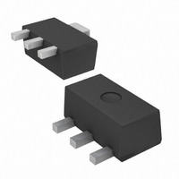
... Device Schematic Pin Out Configuration Symbol V CBO V CEO V EBO CRM Symbol 25°C R θ 25°C R θ STG 2 copper pad layout www.diodes.com DSS4540X NPN SURFACE MOUNT TRANSISTOR Value Unit Value Unit 0.9 W 139 °C 62.5 °C/W -55 to +150 °C December 2008 © Diodes Incorporated ...
Page 2
... Note 5 2.0 1.5 1.0 0 100 125 150 ° www.diodes.com DSS4540X Max Unit Test Conditions ⎯ 100μA C ⎯ 10mA C ⎯ 100μA E 100 30V μ 30V 150°C ...
Page 3
... T = -55° 25° 85°C 0 150° 0.001 Fig. 6 Typical Base-Emitter Saturation Voltage 1,000 f = 1MHz 100 10 C obo 100MHz 100 www.diodes.com DSS4540X 150° 85° 25° -55°C A 0.01 0 COLLECTOR CURRENT (mA) C vs. Collector Current / 0.01 0 COLLECTOR CURRENT (mA) C vs. Collector Current = 10V ...
Page 4
... Ordering Information (Note 7) Part Number DSS4540X-13 Notes: 7. For packaging details our website at http://www.diodes.com/datasheets/ap02007.pdf. Marking Information Package Outline Dimensions Suggested Pad Layout X3 Diodes Incorporated and its subsidiaries reserve the right to make modifications, enhancements, improvements, corrections or other changes without further notice to any product herein. Diodes Incorporated does not assume any liability arising out of the application or use of any product described herein ...