PUMD15,115 NXP Semiconductors, PUMD15,115 Datasheet - Page 4
PUMD15,115
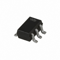
Manufacturer Part Number
PUMD15,115
Description
TRANS NPN/PNP 50V 100MA SOT363
Manufacturer
NXP Semiconductors
Datasheet
1.PUMD15115.pdf
(10 pages)
Specifications of PUMD15,115
Package / Case
SC-70-6, SC-88, SOT-363
Transistor Type
1 NPN, 1 PNP - Pre-Biased (Dual)
Current - Collector (ic) (max)
100mA
Voltage - Collector Emitter Breakdown (max)
50V
Resistor - Base (r1) (ohms)
4.7K
Resistor - Emitter Base (r2) (ohms)
4.7K
Dc Current Gain (hfe) (min) @ Ic, Vce
30 @ 10mA, 5V
Vce Saturation (max) @ Ib, Ic
150mV @ 500µA, 10mA
Current - Collector Cutoff (max)
1µA
Power - Max
300mW
Mounting Type
Surface Mount
Configuration
Dual
Transistor Polarity
NPN/PNP
Typical Input Resistor
4.7 KOhms
Typical Resistor Ratio
1
Mounting Style
SMD/SMT
Collector- Emitter Voltage Vceo Max
50 V
Peak Dc Collector Current
100 mA
Power Dissipation
200 mW
Maximum Operating Temperature
+ 150 C
Emitter- Base Voltage Vebo
10 V
Minimum Operating Temperature
- 65 C
Lead Free Status / RoHS Status
Lead free / RoHS Compliant
Frequency - Transition
-
Lead Free Status / RoHS Status
Lead free / RoHS Compliant, Lead free / RoHS Compliant
Other names
934057891115
PUMD15 T/R
PUMD15 T/R
PUMD15 T/R
PUMD15 T/R
Available stocks
Company
Part Number
Manufacturer
Quantity
Price

Part Number:
PUMD15,115
Manufacturer:
NEXPERIA/安世
Quantity:
20 000


NXP Semiconductors
6. Thermal characteristics
7. Characteristics
PEMD15_PUMD15_3
Product data sheet
Table 7.
[1]
[2]
Table 8.
T
Symbol
Per transistor
R
Per device
R
Symbol
Per transistor; for the PNP transistor with negative polarity
I
I
I
h
V
V
V
R1
R2/R1
C
CBO
CEO
EBO
amb
FE
CEsat
I(off)
I(on)
th(j-a)
th(j-a)
c
Device mounted on a FR4 PCB, single-sided copper, tin-plated and standard footprint.
Reflow soldering is the only recommended soldering method.
= 25 C unless otherwise specified.
Parameter
collector-base cut-off
current
collector-emitter
cut-off current
emitter-base cut-off
current
DC current gain
collector-emitter
saturation voltage
off-state input voltage V
on-state input voltage V
bias resistor 1 (input)
bias resistor ratio
collector capacitance V
Thermal characteristics
Characteristics
Parameter
thermal resistance from
junction to ambient
thermal resistance from
junction to ambient
TR1 (NPN)
TR2 (PNP)
SOT363
SOT666
SOT363
SOT666
NPN/PNP resistor-equipped transistors; R1 = 4.7 k , R2 = 4.7 k
Rev. 03 — 2 September 2009
Conditions
V
V
V
T
V
V
I
f = 1 MHz
C
j
CB
CE
CE
EB
CE
CE
CE
CB
= 150 C
= 10 mA; I
Conditions
in free air
in free air
= 5 V; I
= 50 V; I
= 30 V; I
= 30 V; I
= 5 V; I
= 5 V; I
= 0.3 V; I
= 10 V; I
C
C
C
E
B
B
B
E
= 0 A
= 10 mA
= 100 A
C
= 0 A
= 0 A
= 0 A;
= 0.5 mA
= i
= 20 mA
e
= 0 A;
PEMD15; PUMD15
[1][2]
[1][2]
[1]
[1]
Min
-
-
-
-
Min
-
-
-
-
30
-
-
2.5
3.3
0.8
-
-
Typ
-
-
-
-
Typ
-
-
-
-
-
-
1.1
1.9
4.7
1
-
-
© NXP B.V. 2009. All rights reserved.
Max
625
625
416
416
Max
100
1
50
0.9
-
150
0.5
-
6.1
1.2
2.5
3
Unit
K/W
K/W
K/W
K/W
4 of 10
Unit
nA
mA
mV
V
V
k
pF
pF
A
A
Related parts for PUMD15,115
Image
Part Number
Description
Manufacturer
Datasheet
Request
R

Part Number:
Description:
Digital Transistors TRNS DOUBL RET TAPE7
Manufacturer:
NXP Semiconductors
Datasheet:

Part Number:
Description:
Npn/pnp Resistor-equipped Transistors R1 = 4.7 Kohm R2 = 4.7 Kohmfeatures Built-in Bias Resistors Simplified Circuit Design Reduction of Component Count Reduced Pick and Place Costs. Applications Low Current Peripheral Driver Replacement of General P
Manufacturer:
Philips Semiconductors / NXP Semiconductors

Part Number:
Description:
TRANS ARRAY NPN/PNP SOT-363
Manufacturer:
NXP Semiconductors
Datasheet:

Part Number:
Description:
NXP Semiconductors designed the LPC2420/2460 microcontroller around a 16-bit/32-bitARM7TDMI-S CPU core with real-time debug interfaces that include both JTAG andembedded trace
Manufacturer:
NXP Semiconductors
Datasheet:

Part Number:
Description:
NXP Semiconductors designed the LPC2458 microcontroller around a 16-bit/32-bitARM7TDMI-S CPU core with real-time debug interfaces that include both JTAG andembedded trace
Manufacturer:
NXP Semiconductors
Datasheet:
Part Number:
Description:
NXP Semiconductors designed the LPC2468 microcontroller around a 16-bit/32-bitARM7TDMI-S CPU core with real-time debug interfaces that include both JTAG andembedded trace
Manufacturer:
NXP Semiconductors
Datasheet:
Part Number:
Description:
NXP Semiconductors designed the LPC2470 microcontroller, powered by theARM7TDMI-S core, to be a highly integrated microcontroller for a wide range ofapplications that require advanced communications and high quality graphic displays
Manufacturer:
NXP Semiconductors
Datasheet:
Part Number:
Description:
NXP Semiconductors designed the LPC2478 microcontroller, powered by theARM7TDMI-S core, to be a highly integrated microcontroller for a wide range ofapplications that require advanced communications and high quality graphic displays
Manufacturer:
NXP Semiconductors
Datasheet:
Part Number:
Description:
The Philips Semiconductors XA (eXtended Architecture) family of 16-bit single-chip microcontrollers is powerful enough to easily handle the requirements of high performance embedded applications, yet inexpensive enough to compete in the market for hi
Manufacturer:
NXP Semiconductors
Datasheet:
Part Number:
Description:
The XA-S3 device is a member of Philips Semiconductors? XA(eXtended Architecture) family of high performance 16-bitsingle-chip microcontrollers
Manufacturer:
NXP Semiconductors
Datasheet:

Part Number:
Description:
The NXP BlueStreak LH75401/LH75411 family consists of two low-cost 16/32-bit System-on-Chip (SoC) devices
Manufacturer:
NXP Semiconductors
Datasheet:
Part Number:
Description:
The NXP LPC3130/3131 combine an 180 MHz ARM926EJ-S CPU core, high-speed USB2
Manufacturer:
NXP Semiconductors
Datasheet:
Part Number:
Description:
The NXP LPC3141 combine a 270 MHz ARM926EJ-S CPU core, High-speed USB 2
Manufacturer:
NXP Semiconductors
Part Number:
Description:
The NXP LPC3143 combine a 270 MHz ARM926EJ-S CPU core, High-speed USB 2
Manufacturer:
NXP Semiconductors