PKR4110BSI Ericsson Power Modules, PKR4110BSI Datasheet - Page 17
PKR4110BSI
Manufacturer Part Number
PKR4110BSI
Description
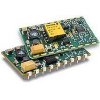
Module DC-DC 1-OUT 3.3V 4.5A 14.85W 18-Pin SMD
Manufacturer
Ericsson Power Modules
Type
Step Downr
Series
PKRr
Datasheet
1.PKR4928ASI.pdf
(36 pages)
Specifications of PKR4110BSI
Package
18SMD
Output Current
4.5 A
Output Voltage
3.3 V
Input Voltage
36 to 75 V
Number Of Outputs
1
Output Power
14.85 W
Product
Isolated
Input Voltage Range
36 V to 75 V
Output Voltage (channel 1)
3.3 V
Output Current (channel 1)
4.5 A
Isolation Voltage
1.5 KV
Package / Case Size
MacroDens
Output Type
Isolated
Lead Free Status / Rohs Status
Lead free / RoHS Compliant


+12V, 0.25A / -12V, 0.25A / 6W Dual, Electrical
Specification
T
Typical values given at: T
V
V
V
C
P
SVR
η
P
P
P
f
V
V
V
t
t
t
I
I
I
V
Note 1: Output filter according to Ripple & Noise section
Note 2: Output voltage on Output 2 is negative (-12V)
Note 3: Can be adjusted to 14.4V. Over 13.8V output voltage, the input voltage range is limited to 38…65V
Prepared (also subject responsible if other)
ESKEVIN
Approved
SEC/D (Julia You)
PKR 4000 series
PKR 4000 series
PKR 4000 series
DC/DC converters, Input 36-75 V, Output up to 1.5 A/7 W
DC/DC converters, Input 36-75 V, Output up to 1.5 A/7 W
DC/DC converters, Input 36-75 V, Output up to 1.5 A/7 W
O
lim
sc
Characteristics
s
tr
r
s
ref
I
Ioff
Ion
O
d
li
RC
Oi
O
tr
Oac
I
= -30 to +85ºC, V
Input voltage range
Turn-off input voltage
Turn-on input voltage
Internal input capacitance
Output power
Supply voltage rejection (ac)
Efficiency
Power Dissipation
Input idling power
Input standby power
Switching frequency
Output voltage initial setting and
accuracy
Output adjust range
Output voltage tolerance band
Idling voltage
Line regulation
Load regulation output 1
Load regulation output 2
Load transient
voltage deviation
Load transient recovery time
Ramp-up time
Start-up time
(from V
Output current
Current limit threshold
Short circuit current
Output ripple & noise
I
connection to 90% of V
(from 10-90% of V
I
= 38 to 72 V, pin 8 connected to pin 9 unless otherwise specified under Conditions.
ref
= +25°C, V
Oi
)
Oi
)
I
= 53 V, max I
Conditions
Decreasing input voltage
Increasing input voltage
Output voltage initial setting
f = 100 Hz sine wave, 1 Vp-p
I
I
I
I
I
I
V
I
T
I
10-100% of max I
I
I
V
I
V
I
V
I
di/dt = 1 A/
I
V
T
See ripple & noise section,
max I
O1
O1
O1
O1
O1
O
O1
O1
O
O1
O2
O1
O1
O1
ref
ref
I
I
I
I
O
= 0 A, V
= 53 V, load step
= 53 V (turned off with RC)
= 0
= 53 V, I
= 53 V, I
= I
= 0.12 A, I
= 0.12 A, I
= 0.12 A, I
= 0.25 A, I
= I
= I
= I
= 0.25 A
= 0.25 A
= 0.1-0.2-0.1 A, I
= I
= 10 V, T
= +25°C, V
= 25ºC
O2
O
O2
O2
O2
O2
, V
= 0.15 A, see Note 2, 3
= 0.25 A
= 0.12…0.25 A
= 0.25 A
= 0.025…0.25 A
Oi
I
Checked
EZYPING
=53 V
O1
O2
μ
ref
s, see Note 1
= 0.025…0.25 A,
= 0.025…0.25 A,
O2
O2
O2
O2
I
< max T
O
= 53 V,
= 0.12 A
= 0.12 A
= 0.12 A, V
= 0.25 A, V
, unless otherwise specified under Conditions.
O
O2
= 0.25 A,
ref
I
I
= 48 V
= 48 V
PRODUCT SPECIFICATION
No.
2/1301-BMR 640 1401+ Uen
Date
2007-8-27
11.83
10.2
11.5
0.35
min
0.4
1.5
13
0
min
412
38
30
32
0
Output 1
-210
12.0
0.76
+56
340
typ
0.2
1.0
3.2
1.1
23
6
Technical Specifi cation
Technical Specifi cation
Technical Specifi cation
EN/LZT 146 302 R6E September 2007
EN/LZT 146 302 R6F November 2007
EN/LZT 146 302 R6G November 2008
© Ericsson Power Modules AB
© Ericsson Power Modules AB
© Ericsson Power Modules AB
Rev
G
12.18
max
13.8
12.5
470
2.9
0.5
1.1
1.7
20
90
50
7
33.4
35.7
100
485
typ
1.0
66
86
86
86
86
32
2
Reference
10.2
11.4
0.35
min
0.4
1.5
13
0
Output 2
12.0
-200
0.76
340
+56
typ
0.2
1.0
3.2
1.1
22
6
max
558
1.3
72
36
38
6
PKR 4621 SI
max
13.8
12.6
455
2.9
0.5
1.1
1.7
20
80
50
7
14 (23)
mVp-p
Unit
mW
mW
kHz
mV
mV
mV
mV
17
dB
ms
ms
ms
μ
W
%
W
V
V
V
V
V
V
V
A
A
A
F
Related parts for PKR4110BSI
Image
Part Number
Description
Manufacturer
Datasheet
Request
R

Part Number:
Description:
37.5-150W DC/DC POWER MODULES
Manufacturer:
Ericsson Power Modules
Part Number:
Description:
DC/DC Power Supply Dual-OUT 3.3V/5V 9.6A/6.4A 40W 10-Pin
Manufacturer:
Ericsson Power Modules
Part Number:
Description:
DC/DC Power Supply Single-OUT 3.3V 20A 66W 8-Pin Quarter-Brick
Manufacturer:
Ericsson Power Modules
Datasheet:
Part Number:
Description:
DC/DC Power Supply Single-OUT 1.8V 50A 90W 11-Pin
Manufacturer:
Ericsson Power Modules
Part Number:
Description:
Module DC-DC 1-OUT 1.8V 30A 54W 9-Pin
Manufacturer:
Ericsson Power Modules

Part Number:
Description:
Module DC-DC 1-OUT 1.8V 60A 108W 11-Pin Half-Brick
Manufacturer:
Ericsson Power Modules
Datasheet:

Part Number:
Description:
Module DC-DC 1-OUT 12V 25A 300W 11-Pin Half-Brick
Manufacturer:
Ericsson Power Modules
Part Number:
Description:
Module DC-DC 1-OUT 5V 20A 100W Quarter-Brick
Manufacturer:
Ericsson Power Modules

Part Number:
Description:
Module DC-DC 1-OUT 12V 6A 72W 8-Pin 1/8-Brick
Manufacturer:
Ericsson Power Modules
Datasheet:
Part Number:
Description:
Module DC-DC 1-OUT 5.05V 2A 10W 18-Pin SMD
Manufacturer:
Ericsson Power Modules
Part Number:
Description:
Manufacturer:
Ericsson Power Modules
Datasheet:

Part Number:
Description:
Module DC-DC 1-OUT 5V 60A 300W 11-Pin Half-Brick Tray
Manufacturer:
Ericsson Power Modules
Part Number:
Description:
Module DC-DC 1-OUT 12V 1A 12W 18-Pin
Manufacturer:
Ericsson Power Modules
Datasheet:
Part Number:
Description:
Module DC-DC 2-OUT 12V/-12V 0.25A 6W 18-Pin SMD
Manufacturer:
Ericsson Power Modules
Part Number:
Description:
Module DC-DC 1-OUT 28V 11A 310W 11-Pin Half-Brick Tray
Manufacturer:
Ericsson Power Modules
Datasheet: