80RIA40 Vishay, 80RIA40 Datasheet - Page 4
80RIA40
Manufacturer Part Number
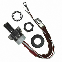
80RIA40
Description
SCR PHASE CONT 400V 125A TO-94
Manufacturer
Vishay
Datasheet
1.80RIA40.pdf
(7 pages)
Specifications of 80RIA40
Scr Type
Standard Recovery
Voltage - Off State
400V
Voltage - Gate Trigger (vgt) (max)
2.5V
Voltage - On State (vtm) (max)
1.6V
Current - On State (it (av)) (max)
80A
Current - On State (it (rms)) (max)
125A
Current - Gate Trigger (igt) (max)
120mA
Current - Hold (ih) (max)
150mA
Current - Off State (max)
15mA
Current - Non Rep. Surge 50, 60hz (itsm)
1900A, 1990A
Operating Temperature
-40°C ~ 125°C
Mounting Type
Chassis, Stud Mount
Package / Case
TO-209AC, TO-94
Current - On State (it (rms) (max)
125A
Breakover Current Ibo Max
1990 A
Rated Repetitive Off-state Voltage Vdrm
400 V
Off-state Leakage Current @ Vdrm Idrm
15 mA
Forward Voltage Drop
1.6 V
Gate Trigger Voltage (vgt)
2.5 V
Maximum Gate Peak Inverse Voltage
10 V
Gate Trigger Current (igt)
120 mA
Holding Current (ih Max)
200 mA
Mounting Style
Stud
Peak Repetitive Off-state Voltage, Vdrm
400V
Gate Trigger Current Max, Igt
120mA
Current It Av
80A
On State Rms Current It(rms)
125A
Peak Non Rep Surge Current Itsm 50hz
1.9kA
Lead Free Status / RoHS Status
Contains lead / RoHS non-compliant
Other names
*80RIA40
VS-80RIA40
VS-80RIA40
VS80RIA40
VS80RIA40
VS-80RIA40
VS-80RIA40
VS80RIA40
VS80RIA40


80RIA...PbF, 81RIA...PbF, 82RIA...PbF Series
Vishay Semiconductors
Note
• The table above shows the increment of thermal resistance R
www.vishay.com
4
R
CONDUCTION ANGLE
thJC
130
120
110
100
CONDUCTION
90
80
180°
120°
90°
60°
30°
Fig. 1 - Current Ratings Characteristics
0
10 20 30 40 50 60 70 80 90
Average On-s tate Current (A)
80RIA S eries
R
30°
thJC
DiodesAmericas@vishay.com, DiodesAsia@vishay.com,
(DC) = 0.30 K/W
120
110
100
60°
90
80
70
60
50
40
30
20
10
For technical questions within your region, please contact one of the following:
0
SINUSOIDAL CONDUCTION
0
90°
Conduc tion Angle
10
120°
Average On-state Current (A)
RMS Limit
180°
120°
90°
60°
30°
20
180°
0.042
0.050
0.064
0.095
0.164
30
Fig. 3 - On-State Power Loss Characteristics
40
Phase Control Thyristors
Conduction Angle
50
(Stud Version), 80 A
80RIA S eries
T = 125°C
J
60
thJC
70
RECTANGULAR CONDUCTION
when devices operate at different conduction angles than DC
80
0
Maximum Allowable Ambient T emperature (°C)
25
0.030
0.052
0.070
0.100
0.165
50
DiodesEurope@vishay.com
130
120
110
100
90
80
70
0
Fig. 2 - Current Ratings Characteristics
75
20
Average On-state Current (A)
30°
40
100
80RIA S eries
R
60°
thJC
90°
60
(DC) = 0.30 K/W
TEST CONDITIONS
125
120°
T
J
Conduction Period
80
= T
180°
J
100
Document Number: 94392
maximum
DC
120 140
Revision: 17-Sep-10
UNITS
K/W
Related parts for 80RIA40
Image
Part Number
Description
Manufacturer
Datasheet
Request
R

Part Number:
Description:
357-036-542-201 CARDEDGE 36POS DL .156 BLK LOPRO
Manufacturer:
Vishay
Datasheet:
Part Number:
Description:
357-036-542-201 CARDEDGE 36POS DL .156 BLK LOPRO
Manufacturer:
Vishay
Datasheet:
Part Number:
Description:
357-036-542-201 CARDEDGE 36POS DL .156 BLK LOPRO
Manufacturer:
Vishay
Datasheet:
Part Number:
Description:
357-036-542-201 CARDEDGE 36POS DL .156 BLK LOPRO
Manufacturer:
Vishay
Datasheet:
Part Number:
Description:
357-036-542-201 CARDEDGE 36POS DL .156 BLK LOPRO
Manufacturer:
Vishay
Datasheet:
Part Number:
Description:
357-036-542-201 CARDEDGE 36POS DL .156 BLK LOPRO
Manufacturer:
Vishay
Datasheet:
Part Number:
Description:
357-036-542-201 CARDEDGE 36POS DL .156 BLK LOPRO
Manufacturer:
Vishay
Datasheet:
Part Number:
Description:
357-036-542-201 CARDEDGE 36POS DL .156 BLK LOPRO
Manufacturer:
Vishay
Datasheet:
Part Number:
Description:
357-036-542-201 CARDEDGE 36POS DL .156 BLK LOPRO
Manufacturer:
Vishay
Datasheet:
Part Number:
Description:
357-036-542-201 CARDEDGE 36POS DL .156 BLK LOPRO
Manufacturer:
Vishay
Datasheet:
Part Number:
Description:
357-036-542-201 CARDEDGE 36POS DL .156 BLK LOPRO
Manufacturer:
Vishay
Datasheet:
Part Number:
Description:
357-036-542-201 CARDEDGE 36POS DL .156 BLK LOPRO
Manufacturer:
Vishay
Datasheet:
Part Number:
Description:
357-036-542-201 CARDEDGE 36POS DL .156 BLK LOPRO
Manufacturer:
Vishay
Datasheet:
Part Number:
Description:
357-036-542-201 CARDEDGE 36POS DL .156 BLK LOPRO
Manufacturer:
Vishay
Datasheet:
Part Number:
Description:
357-036-542-201 CARDEDGE 36POS DL .156 BLK LOPRO
Manufacturer:
Vishay
Datasheet: