ST180C16C0 Vishay, ST180C16C0 Datasheet - Page 3
ST180C16C0
Manufacturer Part Number
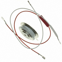
ST180C16C0
Description
SCR PHASE CONT 1600V 350A A-PUK
Manufacturer
Vishay
Specifications of ST180C16C0
Scr Type
Standard Recovery
Voltage - Off State
1600V
Voltage - Gate Trigger (vgt) (max)
3V
Voltage - On State (vtm) (max)
1.96V
Current - On State (it (av)) (max)
350A
Current - On State (it (rms)) (max)
660A
Current - Gate Trigger (igt) (max)
150mA
Current - Hold (ih) (max)
600mA
Current - Off State (max)
30mA
Current - Non Rep. Surge 50, 60hz (itsm)
5000A, 5230A
Operating Temperature
-40°C ~ 125°C
Mounting Type
Chassis Mount
Package / Case
TO-200AB, A-PUK
Current - On State (it (rms) (max)
660A
Mounting Style
SMD/SMT
Peak Repetitive Off-state Voltage, Vdrm
1.6kV
Gate Trigger Current Max, Igt
150mA
Current It Av
350A
On State Rms Current It(rms)
660A
Peak Non Rep Surge Current Itsm 50hz
5kA
Lead Free Status / RoHS Status
Lead free / RoHS Compliant
Other names
*ST180C16C0
VS-ST180C16C0
VS-ST180C16C0
VSST180C16C0
VSST180C16C0
VS-ST180C16C0
VS-ST180C16C0
VSST180C16C0
VSST180C16C0
Available stocks
Company
Part Number
Manufacturer
Quantity
Price
Company:

Part Number:
ST180C16C0
Manufacturer:
Vishay/Semiconductors
Quantity:
135


Blocking
Triggering
Switching
www.irf.com
t
t
di/dt
V
I
V
dv/dt
I
I
P
P
I
+V
-V
I
d
q
GT
DRM
RRM
GM
GD
GD
GT
GM
G(AV)
GM
GM
DC gate voltage not to trigger
DC gate current required
to trigger
DC gate voltage required
to trigger
Parameter
Parameter
Parameter
Maximum peak gate power
Maximum average gate power
Max. peak positive gate current
Maximum peak positive
gate voltage
Maximum peak negative
gate voltage
DC gate current not to trigger
Typical delay time
Typical turn-off time
Max. non-repetitive rate of rise
of turned-on current
Maximum critical rate of rise of
off-state voltage
Max. peak reverse and off-state
leakage current
TYP.
180
2.9
1.8
1.2
ST180C..C
ST180C..C
ST180C..C
90
40
1000
0.25
100
1.0
500
2.0
3.0
5.0
30
10
10
20
MAX.
150
3.0
-
-
-
-
Units Conditions
Units Conditions
Units Conditions
A/µs
V/µs
mA
µs
mA
mA
W
V
A
V
V
T
Gate drive 20V, 20Ω, t
T
Gate current 1A, di
V
I
dv/dt = 20V/µs, Gate 0V 100Ω, t
T
T
T
T
T
T
T
T
T
T
T
T
TM
J
d
J
J
J
J
J
J
J
J
J
J
J
J
J
= T
= T
= T
= T
= T
= - 40°C
= 25°C
= 125°C
= - 40°C
= 25°C
= 125°C
= T
= T
= T
= 0.67% V
= 300A, T
J
J
J
J
J
J
J
J
max, t
max, anode voltage ≤ 80% V
max, rated V
max, t
max, f = 50Hz, d% = 50
max, t
max
max linear to 80% rated V
J
DRM
p
p
p
= T
≤ 5ms
≤ 5ms
≤ 5ms
, T
J
Max. required gate trigger/ cur-
rent/ voltage are the lowest value
which will trigger all units 12V
anode-to-cathode applied
Max. gate current/voltage not to
trigger is the max. value which
will not trigger any unit with rated
V
g
J
max, di/dt = 20A/µs, V
DRM
Bulletin I25164 rev. C 02/00
/dt = 1A/µs
DRM
ST180C..C Series
= 25°C
r
≤ 1µs
anode-to-cathode applied
/V
RRM
applied
p
DRM
= 500µs
DRM
R
= 50V
3
Related parts for ST180C16C0
Image
Part Number
Description
Manufacturer
Datasheet
Request
R


Part Number:
Description:
SIX-CHANNEL DOLBY AC3/MPEG2 AUDIO DECODER
Manufacturer:
STMICROELECTRONICS [STMicroelectronics]
Datasheet:

Part Number:
Description:
357-036-542-201 CARDEDGE 36POS DL .156 BLK LOPRO
Manufacturer:
Vishay
Datasheet:
Part Number:
Description:
357-036-542-201 CARDEDGE 36POS DL .156 BLK LOPRO
Manufacturer:
Vishay
Datasheet:
Part Number:
Description:
357-036-542-201 CARDEDGE 36POS DL .156 BLK LOPRO
Manufacturer:
Vishay
Datasheet:
Part Number:
Description:
357-036-542-201 CARDEDGE 36POS DL .156 BLK LOPRO
Manufacturer:
Vishay
Datasheet:
Part Number:
Description:
357-036-542-201 CARDEDGE 36POS DL .156 BLK LOPRO
Manufacturer:
Vishay
Datasheet:
Part Number:
Description:
357-036-542-201 CARDEDGE 36POS DL .156 BLK LOPRO
Manufacturer:
Vishay
Datasheet:
Part Number:
Description:
357-036-542-201 CARDEDGE 36POS DL .156 BLK LOPRO
Manufacturer:
Vishay
Datasheet:
Part Number:
Description:
357-036-542-201 CARDEDGE 36POS DL .156 BLK LOPRO
Manufacturer:
Vishay
Datasheet:
Part Number:
Description:
357-036-542-201 CARDEDGE 36POS DL .156 BLK LOPRO
Manufacturer:
Vishay
Datasheet:
Part Number:
Description:
357-036-542-201 CARDEDGE 36POS DL .156 BLK LOPRO
Manufacturer:
Vishay
Datasheet:
Part Number:
Description:
357-036-542-201 CARDEDGE 36POS DL .156 BLK LOPRO
Manufacturer:
Vishay
Datasheet:
Part Number:
Description:
357-036-542-201 CARDEDGE 36POS DL .156 BLK LOPRO
Manufacturer:
Vishay
Datasheet: