TYN610RG STMicroelectronics, TYN610RG Datasheet - Page 2
TYN610RG
Manufacturer Part Number
TYN610RG
Description
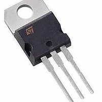
SCR 600V 10A TO-220AB
Manufacturer
STMicroelectronics
Datasheet
1.TYN610RG.pdf
(6 pages)
Specifications of TYN610RG
Scr Type
Standard Recovery
Voltage - Off State
600V
Voltage - Gate Trigger (vgt) (max)
1.5V
Voltage - On State (vtm) (max)
1.6V
Current - On State (it (av)) (max)
6.4A
Current - On State (it (rms)) (max)
10A
Current - Gate Trigger (igt) (max)
15mA
Current - Hold (ih) (max)
30mA
Current - Off State (max)
10µA
Current - Non Rep. Surge 50, 60hz (itsm)
100A, 105A
Operating Temperature
-40°C ~ 125°C
Mounting Type
Through Hole
Package / Case
TO-220AB
Current - On State (it (rms) (max)
10A
Breakover Current Ibo Max
105 A
Rated Repetitive Off-state Voltage Vdrm
0.2 V
Off-state Leakage Current @ Vdrm Idrm
10 uA
Forward Voltage Drop
1.6 V
Gate Trigger Voltage (vgt)
1.5 V
Gate Trigger Current (igt)
15 mA
Holding Current (ih Max)
30 mA
Mounting Style
Through Hole
Lead Free Status / RoHS Status
Lead free / RoHS Compliant
Other names
497-3280
497-3280-5
497-3280
TYN610
497-3280-5
497-3280
TYN610
Available stocks
Company
Part Number
Manufacturer
Quantity
Price
Company:

Part Number:
TYN610RG
Manufacturer:
ST
Quantity:
30 000


TYNx10 Series
Tables 4: Electrical Characteristics (T
Table 5: Thermal Resistance
Figure 1: Maximum average power dissipation
versus average on-state current
2/6
12
10
Symbol
6
4
0
8
2
Symbol
dV/dt
0
I
I
V
V
P(W)
V
R
R
DRM
RRM
I
t
GT
I
I
t
GT
GD
TM
gt
H
L
q
th(j-c)
th(j-a)
= 30°
1
= 60°
V
V
V
I
I
Linear slope up to:
V
I
V
V
dI
T
G
TM
D
D
D
D
DRM
D
2
TM
= 100 mA
Junction to case (D.C.)
Junction to ambient
= 1.2 x I
= 12 V (D.C.)
= V
= V
= 67 % V
= 67 % V
= 20 A
/dt = 30 A/µs
= 90°
= V
3
DRM
DRM
RRM
= 120°
GT
I
T(AV)
4
I
tp = 380 µs
DRM
DRM
R
G
Gate open
L
(A)
= 40 mA dI
5
= 3.3 k
= 180°
Gate open
I
dV
TM
R
6
D
L
= 20 A V
/dt = 50 V/µs
= 33
Test Conditions
7
G
j
/dt = 0.5 A/µs
DC
= 25°C, unless otherwise specified)
360°
8
R
Parameter
= 25 V
9
Figure 2: Correlation between maximum
average power dissipation and maximum
allowable temperature (T
12
10
T
T
T
T
T
8
6
4
2
0
j
j
j
j
j
0
P(W)
= 110°C
= 110°C
= 25°C
= 110°C
= 110°C
= 180°
20
40
MAX.
MAX.
MAX.
MAX.
MAX.
R = 6°C/W
TYP.
TYP.
TYP.
MIN.
MIN.
th
60
T
amb
R = 4°C/W
th
(°C)
80
amb
Value
R = 2°C/W
th
200
1.5
0.2
1.6
and T
50
10
70
15
30
2
2
100
Value
2.5
R = 0°C/W
60
th
lead
120
T
case
)
(°C)
Unit
V/µs
mA
mA
mA
mA
°C/W
°C/W
µA
µs
µs
Unit
V
V
V
140
100
105
110
115
120
125
Related parts for TYN610RG
Image
Part Number
Description
Manufacturer
Datasheet
Request
R

Part Number:
Description:
10A standard SCRs
Manufacturer:
STMicroelectronics
Datasheet:
Part Number:
Description:
STMicroelectronics [RIPPLE-CARRY BINARY COUNTER/DIVIDERS]
Manufacturer:
STMicroelectronics
Datasheet:
Part Number:
Description:
STMicroelectronics [LIQUID-CRYSTAL DISPLAY DRIVERS]
Manufacturer:
STMicroelectronics
Datasheet:

Part Number:
Description:
BOARD EVAL FOR MEMS SENSORS
Manufacturer:
STMicroelectronics
Datasheet:
Part Number:
Description:
NPN TRANSISTOR POWER MODULE
Manufacturer:
STMicroelectronics
Datasheet:
Part Number:
Description:
TURBOSWITCH ULTRA-FAST HIGH VOLTAGE DIODE
Manufacturer:
STMicroelectronics
Datasheet:
Part Number:
Description:
Manufacturer:
STMicroelectronics
Datasheet:
Part Number:
Description:
DIODE / SCR MODULE
Manufacturer:
STMicroelectronics
Datasheet:
Part Number:
Description:
DIODE / SCR MODULE
Manufacturer:
STMicroelectronics
Datasheet:
Part Number:
Description:
Search -----> STE16N100
Manufacturer:
STMicroelectronics
Datasheet:
Part Number:
Description:
Search ---> STE53NA50
Manufacturer:
STMicroelectronics
Datasheet:
Part Number:
Description:
NPN Transistor Power Module
Manufacturer:
STMicroelectronics
Datasheet: