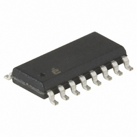
CA3127M Intersil, CA3127M Datasheet - Page 3

CA3127M
Manufacturer Part Number
CA3127M
Description
TRANSISTOR ARRAY NPN 16-SOIC
Manufacturer
Intersil
Datasheet
1.CA3127MZ.pdf
(9 pages)
Specifications of CA3127M
Transistor Type
5 NPN
Voltage - Collector Emitter Breakdown (max)
15V
Frequency - Transition
1.15GHz
Noise Figure (db Typ @ F)
3.5dB @ 100MHz
Gain
27dB ~ 30dB
Power - Max
85mW
Dc Current Gain (hfe) (min) @ Ic, Vce
35 @ 5mA, 6V
Current - Collector (ic) (max)
20mA
Mounting Type
Surface Mount
Package / Case
16-SOIC (3.9mm Width)
Lead Free Status / RoHS Status
Contains lead / RoHS non-compliant
Available stocks
Company
Part Number
Manufacturer
Quantity
Price
Part Number:
CA3127M
Manufacturer:
INTERSIL
Quantity:
20 000
Company:
Part Number:
CA3127M96
Manufacturer:
INT
Quantity:
10 212
Part Number:
CA3127M96
Manufacturer:
HARRIS
Quantity:
20 000
Company:
Part Number:
CA3127MZ
Manufacturer:
INTERSIL
Quantity:
9 642
Part Number:
CA3127MZ
Manufacturer:
INTERSIL
Quantity:
20 000
Electrical Specifications
NOTE:
Test Circuits
Input Resistance
Output Resistance
Input Capacitance
Output Capacitance
Magnitude of Forward Transadmittance
3. When used as a zener for reference voltage, the device must not be subjected to more than 0.1mJ of energy from any possible capacitance or
electrostatic discharge in order to prevent degradation of the junction. Maximum operating zener current should be less than 10mA.
V
I
1000pF
OHMITE
Z144
0.3µH
1.8pF
(NOTE 5)
PARAMETER
8
C
1000
pF
SHIELD
1
FIGURE 1. VOLTAGE-GAIN TEST CIRCUIT USING CURRENT-MIRROR BIASING FOR Q
4
3
6
7
2
3
Q
Q
T A = 25°C
FIGURE 2. 100MHz POWER-GAIN AND NOISE-FIGURE TEST CIRCUIT
2
3
Q
12
5
5
13
620Ω
25kΩ
1µF
(NOTE 5)
1000
0.01
µF
14
pF
560Ω
10kΩ
C
8
2
BIAS-CURRENT
ADJ
Common-Emitter Configuration
V
470pF
CE
= 6V, I
6
7
Q
8.2
kΩ
3
1000
1000
CA3127
CA3127
750Ω
1%
pF
pF
V+
1.5 - 8pF
C
TEST CONDITIONS
0.01µF
0.47µH
= 1mA, f = 200 MHz
470pF
51Ω
V
TEST
POINT
+12V
I
GEN
4
NOTES:
R
4. This circuit was chosen because it conveniently
5. E.F. Johnson number 160-104-1 or equivalent.
L
V
2
3
O
represents a close approximation in performance to a
properly unilateralized single transistor of this type. The
use of Q
simplified biasing. The use of the cascode circuit in no
way implies that the transistors cannot be used
individually.
Q
2
470
pF
V
O
3
in a current-mirror configuration facilitates
0.01
µF
1µF
MIN
-
-
-
-
-
TYP
400
4.6
3.7
24
2
2
MAX
-
-
-
-
-
June 5, 2006
UNITS
mS
kΩ
FN662.5
pF
pF
Ω


