BFG21W,115 NXP Semiconductors, BFG21W,115 Datasheet
BFG21W,115
Specifications of BFG21W,115
934047480115
BFG21W T/R


Related parts for BFG21W,115


BFG21W,115 Summary of contents
Page 1
DATA SHEET BFG21W UHF power transistor Product specification Supersedes data of 1997 Nov 21 DISCRETE SEMICONDUCTORS M3D124 1998 Jul 06 ...
Page 2
... NXP Semiconductors UHF power transistor FEATURES High power gain High efficiency 1.9 GHz operating area Linear and non-linear operation. APPLICATIONS Common emitter class-AB output stage in hand held radio equipment at 1.9 GHz such as DECT, PHS, etc. Driver for DCS1800, 1900. ...
Page 3
... NXP Semiconductors UHF power transistor LIMITING VALUES In accordance with the Absolute Maximum Rating System (IEC 134). SYMBOL PARAMETER V collector-base voltage CBO V collector-emitter voltage CEO V emitter-base voltage EBO I collector current (DC total power dissipation tot T storage temperature stg T operating junction temperature j Note the temperature at the soldering point of the emitter pins. ...
Page 4
... NXP Semiconductors UHF power transistor CHARACTERISTICS = 25 C unless otherwise specified SYMBOL PARAMETER V collector-base breakdown voltage (BR)CBO V collector-emitter breakdown voltage (BR)CEO V collector-emitter breakdown voltage (BR)CER V emitter-base breakdown voltage (BR)EBO I collector leakage current CES h DC current gain FE C collector capacitance c C feedback capacitance ...
Page 5
... NXP Semiconductors UHF power transistor V C handbook, full pagewidth RF input 50 Ω Fig.4 Common emitter test circuit for class-AB operation at 1.9 GHz. List of components used in test circuit (see Figs 4 and 5) COMPONENT DESCRIPTION C1, C5 multilayer ceramic chip capacitor; note 1 C2 multilayer ceramic chip capacitor; note 1 ...
Page 6
... NXP Semiconductors UHF power transistor handbook, full pagewidth C1 input Dimensions in mm. The components are situated on one side of the copper-clad PTFE fibre-glass board, the other side is unetched and serves as a ground plane. Earth connections from the component side to the ground plane are made by through metallization. ...
Page 7
... NXP Semiconductors UHF power transistor 10 handbook, halfpage Z i (Ω 1.8 1. dBm Fig.6 Input impedance as function of frequency (series components); typical values. 1998 Jul 06 MGM223 handbook, halfpage 1.95 2.0 f (GHz) 60 Fig (Ω −4 −8 1.8 1.85 1.9 60 C. ...
Page 8
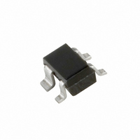
... NXP Semiconductors UHF power transistor PACKAGE OUTLINE Plastic surface-mounted package; reverse pinning; 4 leads DIMENSIONS (mm are the original dimensions UNIT max 0.4 0.7 1.1 mm 0.1 0.8 0.3 0.5 OUTLINE VERSION IEC SOT343R 1998 Jul scale 0.25 2.2 1.35 1.3 1.15 0.10 1.8 1 ...
Page 9
... In no event shall NXP Semiconductors be liable for any indirect, incidental, punitive, special or consequential damages (including - without limitation - lost profits, lost savings, business interruption, costs related to the ...
Page 10
... NXP Semiconductors’ specifications such use shall be solely at customer’s own risk, and (c) customer fully indemnifies NXP Semiconductors for any liability, damages or failed product claims resulting from customer design and use of the product for automotive applications beyond NXP Semiconductors’ ...
Page 11
... Interface, Security and Digital Processing expertise Customer notification This data sheet was changed to reflect the new company name NXP Semiconductors, including new legal definitions and disclaimers. No changes were made to the technical content, except for package outline drawings which were updated to the latest version. ...