FGG.0B.304.CLAD52Z LEMO, FGG.0B.304.CLAD52Z Datasheet - Page 201
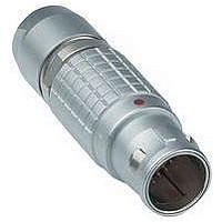
FGG.0B.304.CLAD52Z
Manufacturer Part Number
FGG.0B.304.CLAD52Z
Description
Conn Circular M 4 POS Solder ST Cable Mount 4 Terminal 1 Port
Manufacturer
LEMO
Type
Circularr
Series
Br
Datasheet
1.FGG.1B.304.CLAZ.pdf
(212 pages)
Specifications of FGG.0B.304.CLAD52Z
Gender
PL
Termination Method
Solder
Mounting
Cable Mount
Body Orientation
Straight
Connector Body Material
Brass
Contact Gender
Pin
Connector Mounting
Cable
Insert Arrangement
304
Connector Type
Circular Industrial
Lead Free Status / RoHS Status


Mechanical latching characteristics
F
F
F
Electromagnetic compatibility (EMC)
and shielding efficiency
The electromagnetic compatibility of a device can only be ensu-
red by meeting a number of basic rules with the design of the
device and by carefully selecting components, cables and
connectors.
Electrical and electronic devices are to be designed to ensure
the following:
a) reduce the emission of generated electromagnetic
b) electromagnetic immunity against electromagnetic
When selecting a connector, screen or shielding efficiency
and low resistance to electric continuity between the cable
and the connector should be considered.
The design of LEMO connectors with metal shell and ear-
thing crown guarantee optimum shielding efficiency in all
applications where electromagnetic compatibility (EMC) is
critical.
The performance of a connector is measured through
shielding efficiency, a value that represents the ratio between
the electromagnetic field on the outside and the inside of the
shell. Our measurements are carried out according to the IEC
60169-1-3 standard.
v
d
a
: average latching force.
: average unmating force with axial pull on
: average pull force with axial pull on
disturbance to a level where radios and telecommunication
and other devices can properly function;
disturbance so that they can properly function.
the outer shell.
the collet nut
Fd
Fv
Fa
Standard series
Watertight series
Keyed watertight series
Notes: forces were measured on outer shells not fitted with contacts.
Mechanical endurance: 5000 cycles.
Mechanical endurance represents the number of cycles after which the latching sys-
tem is still effective (1 cycle = 1 latching/unlatching at 300 cycles per hour). The values
were measured according to the standard IEC 60512-7 test 13a.
1N = 0.102 kg.
Force
Force
Force
(N)
(N)
(N)
Fv
Fd
Fa
Fv
Fd
Fa
Fv
Fd
Fa
The performance of S and B series connectors is compa-
rable to the results of measurements carried out on a pair
of FGG + PHG.1B connectors.
The performance of E and K series connectors is compa-
rable to the results of measurements carried out on a pair
of FGG + PHG.1K connectors.
120 140 300 250 400 350 500 650 750 900
250 300 400 550 700 800 900
250 300 400 550 700 800
0E 1E 2E 3E
0K 1K 2K 3K
00 0S 1D 1S
14
14
9
7
9
9
-10
-15
-20
-25
-30
-35
(dBOhm)
-5
14
16
16 20
10
10 13
5
0
9
14 15 12 17 20 40
11 10 12 11 14 25
20 32
13 25
Series
FGG + PHG.1B
Series
32 65
25 40
2C 2S 3S 4S 5S 6S
4E 5E 6E
4K 5K
65 85 100
40 60 75
Series
85
60
150 150 150 150 150 150
Frequency
0F 1F 2F 3F
6
8
Keyed series
120 250 300 400 400 550 700 800
00 0B 1B 2B 2G 3B 4B 5B
9
7
6
8
FGG + PHG.1K
60 70
40 55
10
Series
8
9
8
11 16
14 15 12 17 39 48
11 12 12 14 38 38
9
14
4F 5F
Series
21
24
®
(dB)
100
110
30
40
50
60
70
80
90
(Hz)
199
®
Related parts for FGG.0B.304.CLAD52Z
Image
Part Number
Description
Manufacturer
Datasheet
Request
R

Part Number:
Description:
RF Connectors ADAPTOR SOCKET TO BNC PLUG
Manufacturer:
LEMO
Datasheet:

Part Number:
Description:
RF Connectors ADAPT-BNC(UG88U)COAX
Manufacturer:
LEMO
Datasheet:
Part Number:
Description:
RF Connectors BNC ADAPTER 50 OHM
Manufacturer:
LEMO
Datasheet:

Part Number:
Description:
LEMO, SPRING LOADED DUSTCAP
Manufacturer:
LEMO
Datasheet:

Part Number:
Description:
Circular Push Pull Connectors CONNECTOR WRENCH FOR LEMO
Manufacturer:
LEMO
Part Number:
Description:
Specifications: Connector Type: Plug, Male Pins ; Shell Size - Insert: 114 ; Mounting Type: Free Hanging (In-Line) ; Fastening Type: Threaded ; Features: Shielded ; Packaging: Bulk ; Number of Positions: 114 ; Termination: Crimp ; Shell Material, Fin
Manufacturer:
LEMO
Part Number:
Description:
Specifications: Connector Style: - ; Connector Type: Plug ; Simplex/Duplex: Duplex ; Mode: Singlemode ; Fiber Diameter: 125
Manufacturer:
LEMO