MRF7S19170HSR3 Freescale Semiconductor, MRF7S19170HSR3 Datasheet
MRF7S19170HSR3
Specifications of MRF7S19170HSR3


Related parts for MRF7S19170HSR3

MRF7S19170HSR3 Summary of contents
Page 1
... MHz AVG CASE 465B - 03, STYLE 1 MRF7S19170HR3 CASE 465C - 02, STYLE 1 MRF7S19170HSR3 Symbol V DSS stg Symbol R θJC MRF7S19170HR3 MRF7S19170HSR3 Rev. 1, 12/2008 SINGLE W - CDMA LATERAL N - CHANNEL RF POWER MOSFETs NI - 880 NI - 880S Value Unit - 0.5, +65 Vdc - 6.0, +10 Vdc 32, +0 Vdc - 65 to +150 °C 150 °C 225 °C ...
Page 2
... Output Peak - to - Average Ratio @ 0.01% Probability on CCDF Adjacent Channel Power Ratio Input Return Loss Parameter measured on Freescale Test Fixture, due to resistive divider network on the board. Refer to Test Circuit GG GS(Q) schematic. 2. Part internally matched both on input and output. MRF7S19170HR3 MRF7S19170HSR3 2 = 25°C unless otherwise noted) C Symbol I DSS I DSS I ...
Page 3
... Min Typ Max = 1400 mA, 1930 - 1990 MHz Bandwidth — 25 — — 0.5 — — 2.06 — — 4.7 — — 16 — — 0.015 — — 0.01 — MRF7S19170HR3 MRF7S19170HSR3 Unit MHz dB ° ns ° dB/°C dBm/°C 3 ...
Page 4
... Chip Capacitor C12 1.5 pF Chip Capacitor C13 0.3 pF Chip Capacitor C14 0.8 pF Chip Capacitor C19 470 μ Electrolytic Capacitor, Axial R1 kΩ, 1/4 W Chip Resistors R3 10 Ω, 1/4 W Chip Resistor MRF7S19170HR3 MRF7S19170HSR3 4 Z20 Z7 C8 C15 Z10 Z11 Z12 Z13 DUT C14 ...
Page 5
... Figure 2. MRF7S19170HR3(HSR3) Test Circuit Component Layout RF Device Data Freescale Semiconductor C19 C8 C15 C16 C10 C11 C14 C13 C12 C17 C18 C9 MRF7S19170H Rev 0 MRF7S19170HR3 MRF7S19170HSR3 5 ...
Page 6
... DQ 1750 mA 17 1400 mA 1050 mA 16 700 OUTPUT POWER (WATTS) PEP out Figure 5. Two - Tone Power Gain versus Output Power MRF7S19170HR3 MRF7S19170HSR3 6 TYPICAL CHARACTERISTICS Vdc (Avg.), I DD out DQ Single−Carrier W−CDMA, 3.84 MHz Channel Bandwidth, PAR = 7 0.01% Probability (CCDF) 1900 1920 1940 ...
Page 7
... DQ IM3−U IM3−L IM5−U IM5−L 10 TWO−TONE SPACING (MHz) versus Tone Spacing 50 Ideal Actual −30_C T = −30_C C 25_C 25_C 85_C 85_C Vdc 1400 1960 MHz 10 100 P , OUTPUT POWER (WATTS) CW out versus CW Output Power MRF7S19170HR3 MRF7S19170HSR3 100 400 7 ...
Page 8
... W−CDMA. ACPR Measured in 3.84 MHz Channel Bandwidth @ "5 MHz Offset. 0.001 PAR = 7 0.01% Probability on CCDF 0.0001 PEAK−TO−AVERAGE (dB) Figure 14. CCDF W - CDMA 3GPP, Test Model 1, 64 DPCH, 50% Clipping, Single - Carrier Test Signal MRF7S19170HR3 MRF7S19170HSR3 8 TYPICAL CHARACTERISTICS 1400 1960 MHz ...
Page 9
... Z = Test circuit impedance as measured from source gate to ground Test circuit impedance as measured load from drain to ground. Device Input Under Matching Test Network Z Z source load Output Matching Network MRF7S19170HR3 MRF7S19170HSR3 9 ...
Page 10
... P , INPUT POWER (dBm) in NOTE: Measured in a Peak Tuned Load Pull Fixture Test Impedances per Compression Level Z source Ω P3dB 2.34 - j9.24 Figure 17. Pulsed CW Output Power versus Input Power MRF7S19170HR3 MRF7S19170HSR3 10 62 Ideal P3dB = 54.9 dBm (310 P1dB = 54.14 dBm 56 Actual (259 W) ...
Page 11
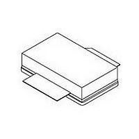
... N 0.871 0.889 19.30 22.60 R 0.515 0.525 13.10 13.30 S 0.515 0.525 13.10 13.30 aaa 0.007 REF 0.178 REF F bbb 0.010 REF 0.254 REF ccc 0.015 REF 0.381 REF STYLE 1: PIN 1. DRAIN 2. GATE 3. SOURCE MRF7S19170HR3 MRF7S19170HSR3 5.08 1.14 0.15 1.70 5.33 11 ...
Page 12
... Replaced Fig. 13, MTTF versus Junction Temperature with updated graph. Removed Amps operating characteristics and location of MTTF calculator for device • Deleted output signal data from Fig. 14, CCDF W - CDMA 3GPP, Test Model 1, 64 DPCH, 50% Clipping, Single - Carrier Test Signal MRF7S19170HR3 MRF7S19170HSR3 12 PRODUCT DOCUMENTATION REVISION HISTORY ...
Page 13
... Semiconductor was negligent regarding the design or manufacture of the part. Freescalet and the Freescale logo are trademarks of Freescale Semiconductor, Inc. All other product or service names are the property of their respective owners. © Freescale Semiconductor, Inc. 2006, 2008. All rights reserved. MRF7S19170HR3 MRF7S19170HSR3 13 ...