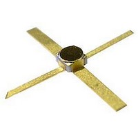
ATF-36077-TR1 Avago Technologies US Inc., ATF-36077-TR1 Datasheet - Page 2

ATF-36077-TR1
Manufacturer Part Number
ATF-36077-TR1
Description
IC PHEMT 2-18GHZ ULT LN 77-SMD
Manufacturer
Avago Technologies US Inc.
Datasheet
1.ATF-36077-TR1.pdf
(4 pages)
Specifications of ATF-36077-TR1
Transistor Type
pHEMT FET
Frequency
12GHz
Gain
12dB
Voltage - Rated
3V
Current Rating
45mA
Noise Figure
0.5dB
Current - Test
10mA
Voltage - Test
1.5V
Power - Output
5dBm
Package / Case
4-SMD (77 Pack)
Power Dissipation Pd
180mW
No. Of Pins
4
Configuration
Single Dual Source
Gate-source Voltage (max)
3V
Operating Temperature (max)
150C
Operating Temperature Classification
Military
Mounting
Surface Mount
Pin Count
4
Lead Free Status / RoHS Status
Lead free / RoHS Compliant
Lead Free Status / RoHS Status
Lead free / RoHS Compliant, Lead free / RoHS Compliant
Available stocks
Company
Part Number
Manufacturer
Quantity
Price
Company:
Part Number:
ATF-36077-TR1
Manufacturer:
AVAGO
Quantity:
729
Part Number:
ATF-36077-TR1
Manufacturer:
AVAGO/安华高
Quantity:
20 000
ATF-36077 Absolute Maximum Ratings
ATF-36077 Electrical Specifications,
T
Note:
1. Measured in a fixed tuned environment with Γ source = 0.54 at 156°; Γ load = 0.48 at 167°.
ATF-36077 Characterization Information,
T
Note:
2. See noise parameter table.
2
C
C
= 25°C, Z
= 25°C, Z
V
Symbol
GS 10 mA
Symbol
Symbol
S
V
P
P
NF
G
12 off
T
V
in max
p 10 %
V
V
1dB
T
NF
g
I
G
P
I
STG
dss
GS
GD
A
DS
D
ch
m
T
A
O
O
= 50 Ω
= 50 Ω
Noise Figure (Tuned Circuit)
Gain at Noise Figure (Tuned Circuit)
Reverse Isolation
Output Power at 1 dB Gain Compression
Gate to Source Voltage for I
Drain – Source Voltage
Gate – Source Voltage
Gate-Drain Voltage
Drain Current
Total Power Dissipation
RF Input Power
Channel Temperature
Storage Temperature
Noise Figure
Gain at NF
Transconductance
Saturated Drain Current
Pinch-off Voltage
,
,
V
V
ds
ds
Parameter
Parameters and Test Conditions
= 1.5 V, I
= 1.5 V, I
[1]
[1]
ds
ds
Parameters and Test Conditions
= 10 mA, (unless otherwise noted).
= 10 mA, (unless otherwise noted).
[3]
DS
= 10 mA
Units
dBm
mW
mA
°C
°C
V
V
V
V
DS
= 1.5 V, I
V
V
DS
DS
= 1.5 V, V
= 1.5 V, V
DS
Maximum
-65 to 150
Absolute
= 10% of I
f = 12.0 GHz
f = 12.0 GHz
-3.5
180
+10
150
I
+3
-3
dss
f = 12 GHz, V
GS
GS
[1]
= 0 V
= 0 V
dss
DS
= 1.5 V, V
Units
mA
mS
dB
dB
V
Thermal Resistance
Notes:
1. Operation of this device above any one of
2. Measured at P
3. Derate at 16.7 mW/°C for T
these parameters may cause permanent
damage.
f = 12 GHz
f = 12 GHz
f = 12 GHz
V
DS
f = 4 GHz
f = 4 GHz
f = 4 GHz
GS
= 1.5 V
= -2 V
Min.
11.0
-1.0
50
15
diss
= 15 mW and T
[2,3]
-0.35
Units
dBm
dBm
12.0
Typ.
0.5
55
25
dB
dB
dB
dB
dB
: θ
V
ch-c
C
> 139°C.
= 60°C/W
-0.15
0.3
Max.
-0.2
ch
Typ.
0.6
0.5
45
17
12
14
5
5
= 100°C.
[2]


