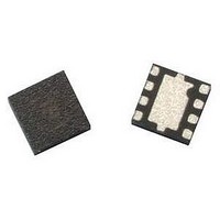
ATF-501P8-TR1 Avago Technologies US Inc., ATF-501P8-TR1 Datasheet - Page 4

ATF-501P8-TR1
Manufacturer Part Number
ATF-501P8-TR1
Description
IC PHEMT 2GHZ 4.5V 280MA 8-LPCC
Manufacturer
Avago Technologies US Inc.
Datasheet
1.ATF-501P8-BLK.pdf
(22 pages)
Specifications of ATF-501P8-TR1
Gain
15dB
Transistor Type
pHEMT FET
Frequency
2GHz
Voltage - Rated
7V
Current Rating
1A
Noise Figure
1dB
Current - Test
280mA
Voltage - Test
4.5V
Power - Output
29dBm
Package / Case
8-LPCC
Drain Source Voltage Vds
4.5V
Continuous Drain Current Id
1A
Power Dissipation Pd
3.5W
Noise Figure Typ
1dB
Rf Transistor Case
LPCC
No. Of Pins
8
Frequency Max
6GHz
Frequency Min
50MHz
Drain Current Idss Max
280mA
Rohs Compliant
Yes
Lead Free Status / RoHS Status
Lead free / RoHS Compliant
Available stocks
Company
Part Number
Manufacturer
Quantity
Price
Company:
Part Number:
ATF-501P8-TR1
Manufacturer:
AVAGO
Quantity:
32 184
Part Number:
ATF-501P8-TR1
Manufacturer:
AVAGO/安华高
Quantity:
20 000
Company:
Part Number:
ATF-501P8-TR1G
Manufacturer:
AVAGO
Quantity:
10 000
RF Input
Figure 7. Simplified schematic of production test board. Primary purpose is to show 15 Ohm series resistor placement in gate supply.
Transmission line tapers, tee intersections, bias lines and parasitic values are not shown.
Gamma Load and Source at Optimum OIP3 and P1dB Tuning Conditions
The device’s optimum OIP3 and P1dB measurements were determined using a load pull system at 4.5V 280 mA and
4.5V 400 mA quiesent bias respectively:
4
Typical Gammas at Optimum OIP3 at 4.5V 280 mA
Freq (GHz)
0.9
2.0
2.4
3.9
Typical Gammas at Optimum P1dB at 4.5V 280mA
Freq (GHz)
0.9
2.0
2.4
3.9
Typical Gammas at Optimum OIP3 at 4.5V 400 mA
Freq (GHz)
0.9
2.0
2.4
3.9
Typical Gammas at Optimum P1dB at 4.5V 400 mA
Freq (GHz)
0.9
2.0
2.4
3.9
1.8 nH
2.2 µF
1.2 pF
Optimized for maximum OIP3 at 4.5V 280 mA
OIP3
46.42
45.50
44.83
43.97
Optimized for maximum P1dB at 4.5V 280 mA
OIP3
39.29
41.79
42.37
42.00
Optimized for maximum OIP3 at 4.5V 400 mA
OIP3
49.15
48.18
47.54
45.44
Optimized for maximum P1dB at 4.5V 400 mA
OIP3
41.78
43.28
42.46
42.94
Supply
Gate
15 nH
15 Ohm
50 Ohm
.02
Gain
16.03
15.07
12.97
6.11
Gain
20.90
14.72
11.25
5.63
Gain
16.85
14.72
12.47
8.05
Gain
21.84
14.83
11.90
7.70
110 Ohm
.03
P1dB
26.67
28.93
29.03
27.33
P1dB
30.49
30.60
30.24
28.26
P1dB
27.86
29.36
29.10
28.49
P1dB
31.23
31.03
30.66
29.56
DUT
110 Ohm
.03
PAE
45.80
50.30
45.70
33.90
PAE
41.00
45.30
39.70
25.80
PAE
44.20
48.89
46.83
37.02
PAE
49.97
44.78
41.00
33.06
50 Ohm
.02
2.2 µF
Gamma Source
0.305 < -140
0.806 < -179.2
0.756 < -167
0.782 < -162
Gamma Source
0.859 < 165
0.76 < -171
0.745 < -166
0.759 < -159
Gamma Source
0.5852 < -135.80
0.7267 < -175.37
0.6155 < -171.71
0.7888 < -148.43
Gamma Source
0.7765 < 168.50
0.8172 < -175.74
0.8149 < -163.78
0.8394 < -151.21
Supply
Drain
1.2 pF
47 nH
3.3 nH
RF Output
Gamma Load
0.577 < 162
0.511 < 164
0.589 < -168
0.524 < -153
Gamma Load
0.757 < 179
0.691 < -168
0.694 < -161
0.708 < -149
Gamma Load
0.4785 < 177.00
0.7338 < 179.56
0.5411 < -172.02
0.5247 < -145.84
Gamma Load
0.7589 < -175.09
0.8011 < -165.75
0.8042 < -161.79
0.7826 < -149.00


