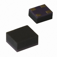
ATF-551M4-TR1 Avago Technologies US Inc., ATF-551M4-TR1 Datasheet - Page 21

ATF-551M4-TR1
Manufacturer Part Number
ATF-551M4-TR1
Description
IC TRANS E-PHEMT GAAS MINIPAK
Manufacturer
Avago Technologies US Inc.
Datasheet
1.ATF-551M4-TR2.pdf
(23 pages)
Specifications of ATF-551M4-TR1
Gain
17.5dB
Mfg Application Notes
ATF-541M4 AppNote
Transistor Type
pHEMT FET
Frequency
2GHz
Voltage - Rated
5V
Current Rating
100mA
Noise Figure
0.5dB
Current - Test
10mA
Voltage - Test
2.7V
Power - Output
14.6dBm
Package / Case
4-MiniPak (1412)
Power Dissipation Pd
270mW
Rf Transistor Case
MiniPak
Frequency Max
10GHz
Noise Figure Typ
0.5dB
Frequency Min
450MHz
Continuous Drain Current Id
0.1µA
Drain Current Idss Max
10mA
Drain Source Voltage Vds
2.7V
Rohs Compliant
Yes
Lead Free Status / RoHS Status
Lead free / RoHS Compliant
Other names
516-1509-2
Available stocks
Company
Part Number
Manufacturer
Quantity
Price
Company:
Part Number:
ATF-551M4-TR1
Manufacturer:
AVAGO
Quantity:
120 000
Part Number:
ATF-551M4-TR1
Manufacturer:
AVAGO/安华高
Quantity:
20 000
Company:
Part Number:
ATF-551M4-TR1G
Manufacturer:
AVAGO
Quantity:
140 000
R7 is chosen to be 1 kΩ. This resistor keeps a small
amount of current flowing through Q2 to help maintain
bias stability. R6 is chosen to be 10 KΩ. This value of re-
sistance is high enough to limit Q1 gate current in the
presence of high RF drive levels as experienced when
Q1 is driven to the P1dB gain compression point. C7
provides a low frequency bypass to keep noise from Q2
effecting the operation of Q1. C7 is typically 0.1 µF.
ATF-551M4 Die Model
ATF-551M4 Minipak Model
SOURCE
21
Port
S1
Num=2
Port
G
Num=1
GATE
Advanced_Curtice2_Model
MESFETM1
NFET=yes
PFET=no
Vto=0.3
Beta=0.444
Lambda=72e-3
Alpha=13
Tau=
Tnom=16.85
Idstc=
Ucrit=-0.72
Vgexp=1.91
Gamds=1e-4
Vtotc=
Betatce=
Rgs=0.5 Ohm
INSIDE Package
Var
Egn
TLINP
TL3
Z=Z2 Ohm
L=23.6 mil
K=K
A=0.000
F=1 GHz
TanD=0.001
C
C1
C=0.28 pF
TLINP
TL9
Z=Z2 Ohm
L=11 mil
K=K
A=0.000
F=1 GHz
TanD=0.001
VAR
VAR1
K=5
Z2=85
Z1=30
L
L1
L=0.234 nH
R=0.001
L
L4
L=0.281 nH
R=0.001
TLINP
TL1
Z=Z2/2 Ohm
L=22 mil
K=K
A=0.000
F=1 GHz
TanD=0.001
Rf=
Gscap=2
Cgs=0.6193 pF
Cgd=0.1435 pF
Gdcap=2
Fc=0.65
Rgd=0.5 Ohm
Rd=2.025 Ohm
Rg=1.7 Ohm
Rs=0.675 Ohm
Ld=
Lg=0.094 nH
Ls=
Cds=0.100 pF
Rc=390 Ohm
GaAsFET
FET1
Mode1=MESFETM1
Mode=Nonlinear
MSUB
MSub2
H=25.0 mil
Er=9.6
Mur=1
Cond=1.0E+50
Hu=3.9e+034 mil
T=0.15 mil
TanD=0
Rough=0 mil
MSub
Crf=0.1 F
Gsfwd=
Gsrev=
Gdfwd=
Gdrev=
R1=
R2=
Vbi=0.95
Vbr=
Vjr=
Is=
Ir=
Imax=
Xti=
Eg=
C=0.046 pF
L
L7
L=0.234 nH
R=0.001
TLINP
TL2
Z=Z2/2 Ohm
L=20 0 mil
K=K
A=0.000
F=1 GHz
TanD=0.001
L
L6
L=0.147 nH
R=0.001
C2
C
Maximum Suggested Gate Current
The maximum suggested gate current for the ATF-
551M4 is 1 mA. Incorporating resistor R5 in the passive
bias network or resistor R6 in the active bias network
safely limits gate current to 500 µA at P1dB drive levels.
In order to minimize component count in the passive
biased amplifier circuit, the 3 resistor bias circuit consist-
ing of R1, R2, and R5 can be simplified if desired. R5 can
be removed if R1 is replaced with a 5.6KΩ resistor and
if R2 is replaced with a 27KΩ resistor. This combination
should limit gate current to a safe level.
N=
Fnc=1 MHz
R=0.08
P=0.2
C=0.1
Taumdl=no
wVgfwd=
wBvgs=
wBvgd=
wBvds=
wldsmax=
wPmax=
AllParams=
TLINP
TL5
Z=Z2 Ohm
L=27.5 mil
K=K
A=0.000
F=1 GHz
TanD=0.001
TLINP
TL7
Z=Z2/2 Ohm
L=5.2 mil
K=K
A=0.000
F=1 GHz
TanD=0.001
SOURCE
DRAIN
Port
S2
Num=4
Port
D
Num=3


