1N5767 Avago Technologies US Inc., 1N5767 Datasheet

DIODE PIN RF SWITCH 100V AXIAL

1N5767

Manufacturer Part Number
1N5767
Description
DIODE PIN RF SWITCH 100V AXIAL
Manufacturer
Avago Technologies US Inc.
Datasheet

Specifications of 1N5767

Diode Type
PIN - Single
Package / Case
Axial
Voltage - Peak Reverse (max)
100V
Current - Max
100mA
Capacitance @ Vr, F
0.4pF @ 50V, 1MHz
Resistance @ If, F
2.5 Ohm @ 100mA, 100MHz
Power Dissipation (max)
250mW
Diode Case Style
Axial Leaded
Series Resistance @ If
2.5ohm
Peak Reflow Compatible (260 C)
No
Leaded Process Compatible
No
Breakdown Voltage
100V
Lead Free Status / RoHS Status
Contains lead / RoHS non-compliant

Available stocks

Company
Part Number
Manufacturer
Quantity
Price
Part Number:
1N5767
Manufacturer:
AVAGO/安华高
Quantity:
20 000
1N5719, 1N5767, 5082-3001, 5082-3039,
5082-3077, 5082-3080/81, 5082-3188, 5082-3379
PIN Diodes for RF Switching and Attenuating
Data Sheet
Maximum Ratings
Junction Operating and
Storage Temperature Range .........................-65°C to +150°C
Power Dissipation 25°C .................................................250 mW
Peak Inverse Voltage (PIV) ...................................... same as V
Maximum Soldering Temperature ............... 260°C for 5 sec
Description/Applications
These general purpose switching diodes are intended for
low power switching applications such as RF duplexers,
antenna switching matrices, digital phase shifters, and time
multiplex filters. The 5082-3188 is optimized for VHF/UHF
bandswitching.
The RF resistance of a PIN diode is a function of the current
flowing in the diode. These current controlled resistors are
specified for use in control applications such as variable RF
attenuators, automatic gain control circuits, RF modula-
tors, electrically tuned filters, analog phase shifters, and
RF limiters.
Outline 15 diodes are available on tape and reel. The tape
and reel specification is patterned after RS-296-D.
(Derate linearly to zero at 150°C)
BR
Features
• Low Harmonic Distortion
• Large Dynamic Range
• Low Series Resistance
• Low Capacitance
Outline 15
CATHODE
DIMENSIONS IN MILLIMETERS AND (INCHES).
0.41 (.016)
0.36 (.014)
1.93 (.076)
1.73 (.068)
25.4 (1.00)
25.4 (1.00)
4.32 (.170)
3.81 (.150)
MIN.
MIN.

Related parts for 1N5767

1N5767 Summary of contents

Page 1

... PIN Diodes for RF Switching and Attenuating Data Sheet Description/Applications These general purpose switching diodes are intended for low power switching applications such as RF duplexers, antenna switching matrices, digital phase shifters, and time multiplex filters. The 5082-3188 is optimized for VHF/UHF bandswitching ...

Page 2

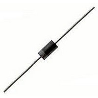
... R Conditions I = 250 mA Measure R I ≤ 10 µA R *The 1N5767 has the additional specifications: τ = 1.0 msec minimum 2 from the glass body. Typical package inductance and ca- pacitance are 2.5 nH and 0.13 pF, respectively. Marking is by digital coding with a cathode band. Minimum Maximum Breakdown Residual Series ...

Page 3

Typical Parameters 25°C (unless otherwise noted) A 100 5082-3001, 3039, 3077, 3080 IN5719 10 1 125°C 25°C –60°C 0.1 0.01 0 0.2 0.4 0.6 0.8 1.0 1.2 V – FORWARD VOLTAGE (V) F Figure 1. Forward Current ...

Page 4

Diode Package Marking 1N5xxx 5082-xxxx would be marked: 1Nx xx xxx xx YWW YWW where xxxx are the last four digits of the 1Nxxxx or the 5082-xxxx part num- ber the last digit of the calendar year. WW ...

Related keywords