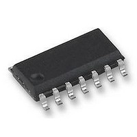
UBA2021T/N2 NXP Semiconductors, UBA2021T/N2 Datasheet - Page 10

UBA2021T/N2
Manufacturer Part Number
UBA2021T/N2
Description
CFL Lamp DRVR 14-Pin SO Tube
Manufacturer
NXP Semiconductors
Datasheet
1.UBA2021PN2112.pdf
(16 pages)
Specifications of UBA2021T/N2
Package
14SO
Driver Type
CFL Lamp
Module Configuration
Half Bridge
Supply Current
1mA
Meter Display Type
Fluorescent Lamp
Supply Voltage Range
9.55V To 10.75V, 11.35V To 12.55V
Driver Case Style
SOIC
No. Of Pins
14
Operating
RoHS Compliant
Operating Supply Voltage
630 V
Maximum Operating Temperature
+ 150 C
Mounting Style
SMD/SMT
Package / Case
SOIC-14
Minimum Operating Temperature
- 40 C
Lead Free Status / Rohs Status
Details
Available stocks
Company
Part Number
Manufacturer
Quantity
Price
Part Number:
UBA2021T/N2
Manufacturer:
NXP/恩智浦
Quantity:
20 000
Company:
Part Number:
UBA2021T/N2,118
Manufacturer:
AD
Quantity:
2 900
Part Number:
UBA2021T/N2,512
Manufacturer:
NXP/恩智浦
Quantity:
20 000
NXP Semiconductors
Table 7.
V
[1]
[2]
[3]
[4]
[5]
[6]
[7]
[8]
[9]
11. Design information
UBA2021_4
Product data sheet
Symbol
f
SYM
RR
R
R
ff
VS
CP(sw)
AV
= 11 V; V
The start-up supply current is specified in a temperature (T
current is < 350 A.
The clamp margin is defined as the voltage difference between turn-on of the clamp and start of oscillation. The clamp is in the off-state
at start of oscillation.
Data sampling of V
The total supply current is specified in a temperature (T
current is < 1.5 mA.
Data sampling of V
Within the allowed range of R
Typical values for the on and off resistances at T
The input current at RHV pin may increase to 1600 A during voltage transient at V
550 A is the oscillator frequency proportional to I
The symmetry SYM
and T2
ff
tot
Characteristics
the time between turn-off of G1 and turn-off of G2.
FS
Parameter
feed-forward frequency
symmetry
ripple rejection
CP switch series resistance
averaging resistor
- V
11.1 Design equations
S1
RS(ctrl)
RS(cap)
= 11 V; T
ff
is calculated from the quotient SYM
f
f
•
B
•
•
•
ff
is performed at the end of conduction of T2.
is performed at the start of conduction of T2.
…continued
=
Bottom frequency:
Feed-forward frequency:
Where:
– X1 = 3.68.
– X2 = 22.28.
–
– R
– C
Operating frequency is the maximum of f
=
RREF
amb
----------------------------------------------------------------------------------------------------------------------- -
2
------------------------------------------------------------------------------------------------------------------------- -
2
= 0.4 s.
, defined as 30 k +10 %.
int
par
= 25 C; all voltages referenced to ground; unless otherwise specified. See
= 3 k .
= 4.7 pF
C
C
CF
CF
+
+
Conditions
I
I
I
f
I
I
C
RHV
RHV
RHV
Vin
CP
CP
C
vj
par
RHV
= 87.5 C are: R
par
= 100 Hz
= 100 A
= 10 A
= 0.75 mA
= 1 mA
= 1 mA
Rev. 04 — 25 July 2008
.
vj
) range of 20 C to +125 C. For T
ff
X 1
vj
= T1
1
X 2 V
----------------------------- - R
) range of 0 C to 125 C. For T
1
I
tot
i RHV
R
/ T2
RREF
G2(on)
RREF
tot
, with T1
and R
–
–
R
int
[9]
int
G1(on)
B
tot
, f
the time between turn-off of G2 and turn-off of G1,
+
ff
in
Min
60.4
80.3
0.9
-
0.75
22.4
+
= 164 , R
. Only for currents I
or f
630 V driver IC for CFL and TL lamps
cm
vj
vj
.
< 0 C and T
< 20 C and T
G2(off)
Typ
63.6
84.5
1
6
1.5
32
and R
RHV
vj
>125 C the start-up supply
G1(off)
beyond approximately
vj
UBA2021
>125 C the total supply
© NXP B.V. 2008. All rights reserved.
Max
66.15
88.2
1.1
-
2.25
41.6
= 100 .
Figure
Unit
kHz
kHz
dB
k
k
10 of 16
8.
(1)
(2)


