AD676BD Analog Devices Inc, AD676BD Datasheet - Page 4
AD676BD
Manufacturer Part Number
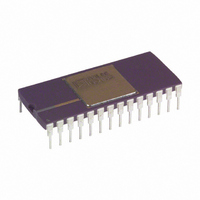
AD676BD
Description
ADC Single SAR 100KSPS 16-Bit Parallel 28-Pin SBCDIP
Manufacturer
Analog Devices Inc
Datasheet
1.AD676JNZ.pdf
(16 pages)
Specifications of AD676BD
Package
28SBCDIP
Resolution
16 Bit
Sampling Rate
100 KSPS
Architecture
SAR
Number Of Analog Inputs
1
Digital Interface Type
Parallel
Input Type
Voltage
Polarity Of Input Voltage
Bipolar
Rohs Status
RoHS non-compliant
Number Of Bits
16
Sampling Rate (per Second)
100k
Data Interface
Parallel
Number Of Converters
2
Power Dissipation (max)
480mW
Voltage Supply Source
Analog and Digital, Dual ±
Operating Temperature
-40°C ~ 85°C
Mounting Type
Through Hole
Package / Case
28-CDIP (0.600", 15.24mm)
For Use With
AD676-EB - BOARD EVAL SAMPLING ADC AD676
Lead Free Status / RoHS Status
Available stocks
Company
Part Number
Manufacturer
Quantity
Price

Part Number:
AD676BD
Manufacturer:
ADI/亚德诺
Quantity:
20 000


AD676
TIMING SPECIFICATIONS
Parameter
Conversion Time
CLK Period
Calibration Time
Sampling Time (Included in t
CAL to BUSY Delay
BUSY to SAMPLE Delay
SAMPLE to BUSY Delay
CLK HIGH
CLK LOW
SAMPLE LOW to 1st CLK Delay
SAMPLE LOW
Output Delay
Status Delay
CAL HIGH Time
NOTES
1
2
3
4
See the “CONVERSION CONTROL” and “AUTOCALIBRATION” sections for detailed explanations of the above timing.
Depends upon external clock frequency; includes acquisition time and conversion time. The maximum conversion time is specified to account for the droop of the
internal sample/hold function. Longer conversion times may degrade performance. See “General Conversion Guidelines” for additional explanation of maximum con-
version time.
580 ns is recommended for optimal accuracy over temperature.
t
BIT 1 – BIT 16
CH
(OUTPUTS)
(OUTPUT)
+ t
SAMPLE
(INPUT)
(INPUT)
CL
BUSY
CLK
= t
Figure 2a. General Conversion Timing
CLK
4
t
S
3
4
t
SC
and must be greater than 480 ns.
t
BS
2
t
SB
(PREVIOUS CONVERSION)
1
2
t
SL
3
t
CLK
C
)
4
5
t
C
BUSY
(T
t
CAL
CLK
CL
MIN
to T
Symbol
t
t
t
t
t
t
t
t
t
t
t
t
t
t
13
C
CLK
CT
S
CALB
BS
SB
CH
CL
SC
SL
OD
SD
CALH
MAX
t
CH
14
V
t
t
CALH
t
CH
CC
15
OD
Figure 1. Calibration Timing
t
= +12 V
CALB
16
t
CL
(NEW DATA)
17
t
t
SD
CLK
t
CT
5%, V
–4–
10
480
2
2
50
50
50
100
50
50
Min
EE
= –12 V
BIT 1 – BIT 16
(OUTPUTS)
(OUTPUT)
SAMPLE
(INPUT)
(INPUT)
BUSY
Figure 2b. Continuous Conversion Timing
CLK
5%, V
t
S
Typ
75
15
125
t
SC
t
BS
t
OD
DD
(PREVIOUS CONVERSION)
t
SB
= +5 V
1
2
t
SL
1000
85,530
150
100
200
Max
3
t
10%, V
CLK
4
5
t
REF
C
t
CL
= 10.0 V)
13
14
1
t
t
Units
ns
t
ns
ns
ns
ns
ns
ns
ns
ns
ns
CH
15
OD
CLK
s
s
s
16
REV. A
(NEW DATA)
17
t
S
t
SD
Related parts for AD676BD
Image
Part Number
Description
Manufacturer
Datasheet
Request
R

Part Number:
Description:
BOARD EVAL SAMPLING ADC AD676
Manufacturer:
Analog Devices Inc
Datasheet:

Part Number:
Description:
±1.7g Dual-Axis IMEMS Accelerometer Evaluation Board
Manufacturer:
Analog Devices Inc
Datasheet:
Part Number:
Description:
Inertial Sensor Evaluation System
Manufacturer:
Analog Devices Inc
Datasheet:
Part Number:
Description:
Manufacturer:
Analog Devices Inc
Datasheet:
Part Number:
Description:
Manufacturer:
Analog Devices Inc
Datasheet:
Part Number:
Description:
Manufacturer:
Analog Devices Inc
Datasheet:
Part Number:
Description:
Manufacturer:
Analog Devices Inc
Datasheet:
Part Number:
Description:
Manufacturer:
Analog Devices Inc
Datasheet:
Part Number:
Description:
Manufacturer:
Analog Devices Inc
Datasheet:
Part Number:
Description:
Manufacturer:
Analog Devices Inc
Datasheet:
Part Number:
Description:
Manufacturer:
Analog Devices Inc
Datasheet:
Part Number:
Description:
Manufacturer:
Analog Devices Inc
Datasheet:
Part Number:
Description:
Manufacturer:
Analog Devices Inc
Datasheet: