AD676BD Analog Devices Inc, AD676BD Datasheet - Page 11
AD676BD
Manufacturer Part Number
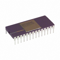
AD676BD
Description
ADC Single SAR 100KSPS 16-Bit Parallel 28-Pin SBCDIP
Manufacturer
Analog Devices Inc
Datasheet
1.AD676JNZ.pdf
(16 pages)
Specifications of AD676BD
Package
28SBCDIP
Resolution
16 Bit
Sampling Rate
100 KSPS
Architecture
SAR
Number Of Analog Inputs
1
Digital Interface Type
Parallel
Input Type
Voltage
Polarity Of Input Voltage
Bipolar
Rohs Status
RoHS non-compliant
Number Of Bits
16
Sampling Rate (per Second)
100k
Data Interface
Parallel
Number Of Converters
2
Power Dissipation (max)
480mW
Voltage Supply Source
Analog and Digital, Dual ±
Operating Temperature
-40°C ~ 85°C
Mounting Type
Through Hole
Package / Case
28-CDIP (0.600", 15.24mm)
For Use With
AD676-EB - BOARD EVAL SAMPLING ADC AD676
Lead Free Status / RoHS Status
Available stocks
Company
Part Number
Manufacturer
Quantity
Price

Part Number:
AD676BD
Manufacturer:
ADI/亚德诺
Quantity:
20 000


Using AGND SENSE to remotely sense the ground potential of
the signal source can be useful if the signal has to be carried
some distance to the A/D converter. Since all IC ground cur-
rents have to return to the power supply and no ground leads
are free from resistance and inductance, there are always some
voltage differences from one ground point in a system to
another.
Over distance this voltage difference can easily amount to sev-
eral LSBs (in a 10 V input span, 16-bit system each LSB is
about 0.15 mV). This would directly corrupt the A/D input sig-
nal if the A/D measures its input with respect to power ground
(AGND) as shown in Figure 5a. To solve this problem the
AD676 offers an AGND SENSE pin. Figure 5b shows how the
AGND SENSE can be used to eliminate the problem in Figure
5a. Figure 5b also shows how the signal wires should be
shielded in a noisy environment to avoid capacitive coupling. If
inductive (magnetic) coupling is expected to be dominant such
as where motors are present, twisted-pair wires should be used
instead.
The digital ground pin is the reference point for all of the digital
signals that operate the AD676. This pin should be connected
to the digital common point in the system. As Figure 4 illus-
trated, the analog and digital grounds should be connected to-
gether at one point in the system, preferably at the AD676.
REV. A
Figure 5a. Input to the A/D Is Corrupted by IR Drop in
Ground Leads: V
SOURCE
SOURCE
Figure 5b. AGND SENSE Eliminates the Problem in
Figure 5a.
GROUND LEAD
GROUND LEAD
V
V
S
S
IN
SHIELDED CABLE
= V
S
V
+ V
I
I
GROUND
GROUND
> 0
> 0
V
AGND
V
AGND
SENSE
AGND
AD676
IN
AD676
IN
TO POWER
SUPPLY GND
TO POWER
SUPPLY GND
–11–
VOLTAGE REFERENCE
The AD676 requires the use of an external voltage reference.
The input voltage range is determined by the value of the refer-
ence voltage; in general, a reference voltage of n volts allows an
input range of n volts. The AD676 is specified for both 10 V
and 5.0 V references. A 10 V reference will typically require
support circuitry operated from 15 V supplies; a 5.0 V refer-
ence may be used with 12 V supplies. Signal-to-noise perfor-
mance is increased proportionately with input signal range. In
the presence of a fixed amount of system noise, increasing the
LSB size (which results from increasing the reference voltage)
will increase the effective S/(N+D) performance. Figure 12
illustrates S/(N+D) as a function of reference voltage. In
contrast, INL will be optimal at lower reference voltage values
(such as 5 V) due to capacitor nonlinearity at higher voltage
values.
During a conversion, the switched capacitor array of the AD676
presents a dynamically changing current load at the voltage ref-
erence as the successive-approximation algorithm cycles through
various choices of capacitor weighting. (See the following sec-
tion “Analog Input” for a detailed discussion of the V
characteristics.) The output impedance of the reference circuitry
must be low so that the output voltage will remain sufficiently
constant as the current drive changes. In some applications, this
may require that the output of the voltage reference be buffered
by an amplifier with low impedance at relatively high frequen-
cies. In choosing a voltage reference, consideration should be
made for selecting one with low noise. A capacitor connected
between REF IN and AGND will reduce the demands on the
reference by decreasing the magnitude of high frequency com-
ponents required to be sourced by the reference.
Figures 6 and 7 represent typical design approaches.
Figure 6 shows a voltage reference circuit featuring the 5 V out-
put AD586. The AD586 is a low cost reference which utilizes a
buried Zener architecture to provide low noise and drift. Over
the 0 C to +70 C range, the AD586L grade exhibits less than
2.25 mV output change from its initial value at +25 C. A noise-
reduction capacitor, C
1.0 F
C
N
8
AD586
+12V
V
4
2
IN
N
, reduces the broadband noise of the
Figure 6.
6
10 F
+
16
13
V
AGND
REF
AD676
AD676
REF
input
Related parts for AD676BD
Image
Part Number
Description
Manufacturer
Datasheet
Request
R

Part Number:
Description:
BOARD EVAL SAMPLING ADC AD676
Manufacturer:
Analog Devices Inc
Datasheet:

Part Number:
Description:
±1.7g Dual-Axis IMEMS Accelerometer Evaluation Board
Manufacturer:
Analog Devices Inc
Datasheet:
Part Number:
Description:
Inertial Sensor Evaluation System
Manufacturer:
Analog Devices Inc
Datasheet:
Part Number:
Description:
Manufacturer:
Analog Devices Inc
Datasheet:
Part Number:
Description:
Manufacturer:
Analog Devices Inc
Datasheet:
Part Number:
Description:
Manufacturer:
Analog Devices Inc
Datasheet:
Part Number:
Description:
Manufacturer:
Analog Devices Inc
Datasheet:
Part Number:
Description:
Manufacturer:
Analog Devices Inc
Datasheet:
Part Number:
Description:
Manufacturer:
Analog Devices Inc
Datasheet:
Part Number:
Description:
Manufacturer:
Analog Devices Inc
Datasheet:
Part Number:
Description:
Manufacturer:
Analog Devices Inc
Datasheet:
Part Number:
Description:
Manufacturer:
Analog Devices Inc
Datasheet:
Part Number:
Description:
Manufacturer:
Analog Devices Inc
Datasheet: