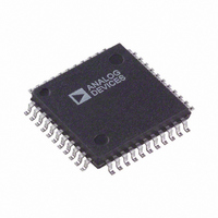
AD6600ASTZ Analog Devices Inc, AD6600ASTZ Datasheet - Page 20

AD6600ASTZ
Manufacturer Part Number
AD6600ASTZ
Description
ADC Single 20MSPS 11-Bit Parallel 44-Pin LQFP
Manufacturer
Analog Devices Inc
Datasheet
1.AD6600ASTZ-REEL.pdf
(24 pages)
Specifications of AD6600ASTZ
Package
44LQFP
Resolution
11 Bit
Sampling Rate
20000 KSPS
Number Of Adcs
1
Number Of Analog Inputs
2
Digital Interface Type
Parallel
Input Type
Voltage
Signal To Noise Ratio
59(Typ) dB
Sample And Hold
Yes
Polarity Of Input Voltage
Bipolar
Number Of Bits
11
Sampling Rate (per Second)
20M
Data Interface
Parallel
Number Of Converters
1
Power Dissipation (max)
976mW
Voltage Supply Source
Single Supply
Operating Temperature
-40°C ~ 85°C
Mounting Type
Surface Mount
Package / Case
44-LQFP
Lead Free Status / RoHS Status
Lead free / RoHS Compliant
Available stocks
Company
Part Number
Manufacturer
Quantity
Price
Company:
Part Number:
AD6600ASTZ
Manufacturer:
Analog Devices Inc
Quantity:
10 000
Part Number:
AD6600ASTZ
Manufacturer:
ADI/亚德诺
Quantity:
20 000
Company:
Part Number:
AD6600ASTZ-REEL
Manufacturer:
Analog Devices Inc
Quantity:
10 000
AD6600
The layout of the Encode circuit is equally critical. Any noise
received on this circuitry will result in corruption in the digitiza-
tion process and lower overall performance. The Encode clock
must be isolated from the digital outputs and the analog inputs.
Evaluation Board
The evaluation board for the AD6600 is straightforward, con-
taining all required circuitry for evaluating the device. The only
external connections required are power supplies, clock and the
analog inputs. The evaluation board includes the option for an
on-board, clock oscillator for encode.
Power to the analog supply pins of the AD6600 is connected via
the power terminal block (TB1). Power for the digital interface
is supplied via Pin 1 of J201, or the VDD e-hole located adja-
cent to J201. The VDD supply can vary between 3.3 V to 5.0 V
and sets the level for the output digital data (J201). The J201
connector mates directly with the AD6620 (Receive Signal
Processor) evaluation board, Part # AD6620S/PCB, allowing
complete evaluation of system performance.
The two analog inputs are connected via SMA connectors
AIN and BIN, which are transformer-coupled to the AD6600
inputs. The transformers have a turns-ratio of 1:4 to match
the input resistance of the AD6600 (200 Ω) to 50 Ω at the
SMA connectors.
Item
1
2
3
4
5
6
7
8
9
10
11
12
13
14
15
16
17
18
Quantity
3
14
2
1
4
2
1
1
1
2
2
1
1
2
3
1
2
1
Reference
AIN, BIN, ENCODE
C1, C102–108, C114, C117–118,
C120–121, C299
C100–101
C111
C112–C113, C115–116
CR1–2
DUT
J1
J201
R1–2
R100–R101
R103
R104
R298–R299
T1–T2, T4
TB1
U201–U202
U204
Table VI. AD6600ST/PCB Bill of Material
The Encode signal may be generated using an on-board crystal
oscillator, U100. If an on-board crystal is used, R104 must be
removed from the board to prevent loading of the oscillator’s
output. The on-board oscillator may be replaced by an external
encode source via the SMA connector labeled ENCODE. If an
external source is used, it must be a high quality and very low
phase noise source. The high IF range of the AD6600 (70 MHz
–250 MHz) demands that the Encode clock be sufficiently pure
to maintain performance.
The AD6600 output data is latched using 74LCX574 (U201,
U202) latches. The clock for these latches is determined by
jumper selection on header J1. The clock can be a delayed ver-
sion of the encode clock (CLKA, CLKB), or the CLK2× gener-
ated by the AD6600. A clock is also distributed with the output
data (J201) that is labeled CLKX (Pin 11, J201). The CLK× is
selected with jumpers on header J1 and can be CLKA, CLKB,
or CLK2×.
The resonant LC filter components (SEL2, C2 and C3) are
omitted. The user must install proper values based on the IF
chosen. See Understanding the External Analog Filter section of
the data sheet for guidelines on selecting these components.
Description
SMA Connector
Ceramic Chip Capacitor 1206, 0.1 µF
Tantalum Chip Capacitor, 10 µF
Ceramic Chip Capacitor 0805, 0.1 µF
Ceramic Chip Capacitor 0508, 0.1 µF
1N2810 Schottky Diode
AD6600AST
20-Pin Double Row Male Header
50-Pin Double Row Male Header, Right Angle
Omitted
Surface Mount Resistor 1206, 10 kΩ
Surface Mount Resistor 1206, 100 Ω
Surface Mount Resistor 1206, 50 Ω
Surface Mount Resistor 1206, 2 kΩ
Surface Mount Transformer Mini-Circuits T4–1T
PCTB2 Terminal Block
74LCX574 Octal Latch
74LVQ00 Two Input NAND Gate


