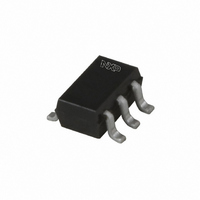
BAP70AM,115 NXP Semiconductors, BAP70AM,115 Datasheet - Page 3

BAP70AM,115
Manufacturer Part Number
BAP70AM,115
Description
DIODE PIN 50V 100MA 6-UMT
Manufacturer
NXP Semiconductors
Type
Attenuatorr
Datasheet
1.BAP70AM135.pdf
(8 pages)
Specifications of BAP70AM,115
Package / Case
SC-70-6, SC-88, SOT-363
Diode Type
PIN - 2 Pair Series
Voltage - Peak Reverse (max)
50V
Current - Max
100mA
Capacitance @ Vr, F
0.25pF @ 20V, 1MHz
Resistance @ If, F
1.9 Ohm @ 100mA, 100MHz
Power Dissipation (max)
300mW
Configuration
Double Dual Series
Reverse Voltage
50 V
Forward Continuous Current
100 mA
Carrier Life
1.25 us
Forward Voltage Drop
1.1 V @ 50 mA
Maximum Diode Capacitance
0.25 pF @ 20 V
Maximum Operating Temperature
+ 150 C
Maximum Series Resistance @ Maximum If
1.9 Ohm @ 100 mA
Maximum Series Resistance @ Minimum If
100 Ohm @ 0.5 mA
Minimum Operating Temperature
- 65 C
Mounting Style
SMD/SMT
Power Dissipation
300 mW
Forward Current
100mA
Forward Voltage
1.1V
Operating Temperature Classification
Military
Mounting
Surface Mount
Typical Carrier Life Time
1.25us
Operating Temperature (max)
150C
Operating Temperature (min)
-65C
Lead Free Status / RoHS Status
Lead free / RoHS Compliant
Lead Free Status / RoHS Status
Lead free / RoHS Compliant, Lead free / RoHS Compliant
Other names
934059306115
BAP70AM T/R
BAP70AM T/R
BAP70AM T/R
BAP70AM T/R
NXP Semiconductors
7. Characteristics
Table 6.
T
BAP70AM
Product data sheet
Symbol
V
I
C
r
τ
L
R
D
amb
L
Fig 1.
S
F
d
= 25
(fF)
C
600
500
400
300
200
d
°
0
f = 1 MHz; T
voltage; typical values
Diode capacitance as a function of reverse
C unless otherwise specified.
Characteristics
Parameter
forward voltage
reverse current
diode capacitance
diode forward resistance
charge carrier life time
series inductance
5
j
= 25 °C.
10
15
Conditions
I
V
see
see
when switched from I
I
I
I
F
R
R
F
R
All information provided in this document is subject to legal disclaimers.
V
V
V
V
I
I
I
I
= 50 mA
= 100 mA; f = 100 MHz
= 6 mA; R
= 3 mA
F
F
F
F
001aaa461
V
= 50 V
R
R
R
R
R
Figure
Figure
= 0.5 mA
= 1 mA
= 10 mA
= 100 mA
= 0 V
= 1 V
= 5 V
= 20 V
(V)
Rev. 2 — 7 September 2010
20
1; f = 1 MHz;
2; f = 100 MHz;
L
= 100 Ω; measured at
F
= 10 mA to
Fig 2.
(Ω)
r
10
10
D
10
10
1
3
2
f = 100 MHz; T
Diode forward resistance as a function of
forward current; typical values
−1
1
j
= 25 °C.
Min
-
-
-
-
-
-
-
-
-
-
-
-
Silicon PIN diode array
Typ
0.9
-
570
400
270
200
77
40
5.4
1.4
1.25
0.6
10
BAP70AM
© NXP B.V. 2010. All rights reserved.
I
F
(mA)
Max
1.1
< 100
-
-
-
250
100
50
7
1.9
-
-
mce007
10
2
Unit
V
nA
fF
fF
fF
fF
Ω
Ω
Ω
Ω
μs
nH
3 of 8


