BFC236652473 Vishay, BFC236652473 Datasheet - Page 15
BFC236652473
Manufacturer Part Number
BFC236652473
Description
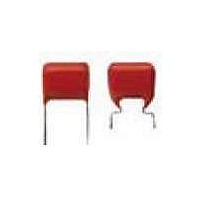
Cap Film 0.047uF 400VDC/220VAC PET 5% 10 X 5 X 13.5mm RDL 7.5mm Loose in Box
Manufacturer
Vishay
Series
MKT 366r
Datasheet
1.BFC236625474.pdf
(20 pages)
Specifications of BFC236652473
Package/case
10(Max) X 5(Max) X 13.5(Max)
Mounting
Through Hole
Capacitance Value
0.047 uF
Voltage
400|220 Vdc|Vac
Dielectric
PET
Lead Pitch For Radial
7.5 mm
Product Length
10(Max) mm
Product Depth
5(Max) mm
Tolerance
5 %
Operating Temperature
-55 to 105 °C
Capacitance
0.047 uF
Voltage Rating
400 Volts
Termination Style
Radial
Dimensions
5 mm Dia. x 4 mm W x 10 mm L x 12 mm H
Lead Spacing
7.5 mm
Operating Temperature Range
0 C to + 85 C
Dissipation Factor Df
75
Product
Metallized Polyester Film Capacitors
Lead Free Status / Rohs Status
Details


POWER DISSIPATION AND MAXIMUM COMPONENT TEMPERATURE RISE
The power dissipation must be limited in order not to exceed the maximum allowed component temperature rise as a function of
the free ambient temperature.
The power dissipation can be calculated according type detail specification “HQN-384-01/101: Technical Information Film
Capacitors”.
The component temperature rise ( T) can be measured (see section “Measuring the Component Temperature” for more details)
or calculated by T = P/G:
MEASURING THE COMPONENT TEMPERATURE
A thermocouple must be attached to the capacitor body as in:
The temperature is measured in unloaded (T
The temperature rise is given by T = T
To avoid radiation or convection, the capacitor should be tested in a wind-free box.
APPLICATION NOTE AND LIMITING CONDITIONS
These capacitors are not suitable for mains applications as across-the-line capacitors without additional protection, as described
hereunder. These mains applications are strictly regulated in safety standards and therefore electromagnetic interference
suppression capacitors conforming the standards must be used.
To select the capacitor for a certain application, the following conditions must be checked:
1. For capacitors connected in parallel, normally the proof voltage and possibly te rated voltage must be reduced. For
2. The peak voltage (U
3. The peak-to-peak voltage (U
4. The voltage pulse slope (dU/dt) shall not exceed the rated voltage pulse slope in an RC-circuit at rated voltage and without
Document Number: 28102
Revision: 22-Dec-10
P = Power dissipation of the component (mW)
G = Heat conductivity of the component (mW/°C)
T = Component temperature rise (°C)
ringing. If the pulse voltage is lower than the rated DC voltage, the rated voltage pulse slope may be multiplied by U
divided by the applied voltage.
For all other pulses following equation must be fulfilled:
T is the pulse duration.
The rated voltage pulse slope is valid for ambient temperatures up to 85 °C. For higher temperatures a derating factor of 3 %
per K shall be applied.
information depending of the capacitance value and the number of parallel connections contact:
2
T
0
dU
------- -
dt
2
dt U
Rdc
P
) shall not be greater than the rated DC voltage (U
dU
------- -
dt
P-P
rated
) shall not be greater than 2 2 x U
C
- T
For technical questions, contact:
MKT Radial Lacquered Type
amb
amb
.
) and maximum loaded condition (T
DC Film Capacitors
RAC
to avoid the ionisation inception level
dc-film@vishay.com
RDC
MKT365, MKT366, MKT367
)
Thermocouple
C
).
Vishay BCcomponents
dc-film@vishay.com
www.vishay.com
RDC
and
43
Related parts for BFC236652473
Image
Part Number
Description
Manufacturer
Datasheet
Request
R

Part Number:
Description:
357-036-542-201 CARDEDGE 36POS DL .156 BLK LOPRO
Manufacturer:
Vishay
Datasheet:
Part Number:
Description:
357-036-542-201 CARDEDGE 36POS DL .156 BLK LOPRO
Manufacturer:
Vishay
Datasheet:
Part Number:
Description:
357-036-542-201 CARDEDGE 36POS DL .156 BLK LOPRO
Manufacturer:
Vishay
Datasheet:
Part Number:
Description:
357-036-542-201 CARDEDGE 36POS DL .156 BLK LOPRO
Manufacturer:
Vishay
Datasheet:
Part Number:
Description:
357-036-542-201 CARDEDGE 36POS DL .156 BLK LOPRO
Manufacturer:
Vishay
Datasheet:
Part Number:
Description:
357-036-542-201 CARDEDGE 36POS DL .156 BLK LOPRO
Manufacturer:
Vishay
Datasheet:
Part Number:
Description:
357-036-542-201 CARDEDGE 36POS DL .156 BLK LOPRO
Manufacturer:
Vishay
Datasheet:
Part Number:
Description:
357-036-542-201 CARDEDGE 36POS DL .156 BLK LOPRO
Manufacturer:
Vishay
Datasheet:
Part Number:
Description:
357-036-542-201 CARDEDGE 36POS DL .156 BLK LOPRO
Manufacturer:
Vishay
Datasheet:
Part Number:
Description:
357-036-542-201 CARDEDGE 36POS DL .156 BLK LOPRO
Manufacturer:
Vishay
Datasheet:
Part Number:
Description:
357-036-542-201 CARDEDGE 36POS DL .156 BLK LOPRO
Manufacturer:
Vishay
Datasheet:
Part Number:
Description:
357-036-542-201 CARDEDGE 36POS DL .156 BLK LOPRO
Manufacturer:
Vishay
Datasheet:
Part Number:
Description:
357-036-542-201 CARDEDGE 36POS DL .156 BLK LOPRO
Manufacturer:
Vishay
Datasheet:
Part Number:
Description:
357-036-542-201 CARDEDGE 36POS DL .156 BLK LOPRO
Manufacturer:
Vishay
Datasheet:
Part Number:
Description:
357-036-542-201 CARDEDGE 36POS DL .156 BLK LOPRO
Manufacturer:
Vishay
Datasheet: