IRFBC40AS Vishay, IRFBC40AS Datasheet
IRFBC40AS
Manufacturer Part Number
IRFBC40AS
Description
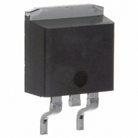
MOSFET N-CH 600V 6.2A D2PAK
Manufacturer
Vishay
Specifications of IRFBC40AS
Fet Type
MOSFET N-Channel, Metal Oxide
Fet Feature
Standard
Rds On (max) @ Id, Vgs
1.2 Ohm @ 3.7A, 10V
Drain To Source Voltage (vdss)
600V
Current - Continuous Drain (id) @ 25° C
6.2A
Vgs(th) (max) @ Id
4V @ 250µA
Gate Charge (qg) @ Vgs
42nC @ 10V
Input Capacitance (ciss) @ Vds
1036pF @ 25V
Power - Max
125W
Mounting Type
Surface Mount
Package / Case
D²Pak, TO-263 (2 leads + tab)
Lead Free Status / RoHS Status
Contains lead / RoHS non-compliant
Other names
*IRFBC40AS
Available stocks
Company
Part Number
Manufacturer
Quantity
Price
Company:

Part Number:
IRFBC40AS
Manufacturer:
IR
Quantity:
12 500


Note
a. See device orientation.
Notes
a. Repetitive rating; pulse width limited by maximum junction temperature (see fig. 11).
b. Starting T
c. I
d. 1.6 mm from case.
e. Uses IRFBC40A, SiHFBC40A data and test conditions.
* Pb containing terminations are not RoHS compliant, exemptions may apply
Document Number: 91113
S11-1053-Rev. C, 30-May-11
THE PRODUCTS DESCRIBED HEREIN AND THIS DOCUMENT ARE SUBJECT TO SPECIFIC DISCLAIMERS, SET FORTH AT
PRODUCT SUMMARY
V
R
Q
Q
Q
Configuration
ORDERING INFORMATION
Package
Lead (Pb)-free and Halogen-free
Lead (Pb)-free
ABSOLUTE MAXIMUM RATINGS (T
PARAMETER
Drain-Source Voltage
Gate-Source Voltage
Continuous Drain Current
Pulsed Drain Current
Linear Derating Factor
Single Pulse Avalanche Energy
Repetitive Avalanche Current
Repetitive Avalanche Energy
Maximum Power Dissipation
Peak Diode Recovery dV/dt
Operating Junction and Storage Temperature Range
Soldering Recommendations (Peak Temperature)
DS
DS(on)
g
gs
gd
SD
(Max.) (nC)
(nC)
(V)
(nC)
6.2 A, dI/dt 88 A/μs, V
G D
D
()
2
PAK (TO-263)
S
J
= 25 °C, L = 29.6 mH, R
a, e
e
c, e
a
a
DD
b
V
GS
V
= 10 V
g
DS
= 25 , I
G
, T
N-Channel MOSFET
J
Single
D
SiHFBC40AS-GE3
IRFBC40ASPbF
SiHFBC40AS-E3
150 °C.
600
42
10
20
2
PAK (TO-263)
This document is subject to change without notice.
AS
C
= 6.2 A (see fig. 12).
D
S
= 25 °C, unless otherwise noted)
Power MOSFET
V
GS
1.2
at 10 V
T
for 10 s
C
= 25 °C
T
T
C
C
= 100 °C
= 25 °C
FEATURES
• Halogen-free According to IEC 61249-2-21
• Low Gate Charge Q
• Improved Gate, Avalanche and Dynamic dV/dt
• Fully Characterized Capacitance and Avalanche Voltage
• Effective C
• Compliant to RoHS Directive 2002/95/EC
APPLICATIONS
• Switch Mode Power Supply (SMPS)
• Uninterruptible Power Supply
• High Speed Power Switching
TYPICAL SMPS TOPOLOGIES
• Single Transistor Forward
Definition
Requirement
Ruggedness
and Current
D
SiHFBC40ASTRL-GE3
IRFBC40ASTRLPbF
SiHFBC40ASTL-E3
2
PAK (TO-263)
SYMBOL
IRFBC40AS, SiHFBC40AS
T
dV/dt
oss
J
V
V
E
E
I
I
P
, T
DM
I
AR
DS
GS
AR
D
AS
D
stg
Specified
a
a
a
g
results in Simple Drive
- 55 to + 150
LIMIT
300
D
SiHFBC40ASTRR-GE3
IRFBC40ASTRRPbF
SiHFBC40ASTR-E3
± 30
600
570
125
6.2
3.9
1.0
6.2
6.0
25
13
2
www.vishay.com/doc?91000
PAK (TO-263)
d
Vishay Siliconix
www.vishay.com
a
a
UNIT
W/°C
V/ns
mJ
mJ
°C
W
V
A
A
a
1
Related parts for IRFBC40AS
Image
Part Number
Description
Manufacturer
Datasheet
Request
R

Part Number:
Description:
357-036-542-201 CARDEDGE 36POS DL .156 BLK LOPRO
Manufacturer:
Vishay
Datasheet:
Part Number:
Description:
357-036-542-201 CARDEDGE 36POS DL .156 BLK LOPRO
Manufacturer:
Vishay
Datasheet:
Part Number:
Description:
357-036-542-201 CARDEDGE 36POS DL .156 BLK LOPRO
Manufacturer:
Vishay
Datasheet:
Part Number:
Description:
357-036-542-201 CARDEDGE 36POS DL .156 BLK LOPRO
Manufacturer:
Vishay
Datasheet:
Part Number:
Description:
357-036-542-201 CARDEDGE 36POS DL .156 BLK LOPRO
Manufacturer:
Vishay
Datasheet:
Part Number:
Description:
357-036-542-201 CARDEDGE 36POS DL .156 BLK LOPRO
Manufacturer:
Vishay
Datasheet:
Part Number:
Description:
357-036-542-201 CARDEDGE 36POS DL .156 BLK LOPRO
Manufacturer:
Vishay
Datasheet:
Part Number:
Description:
357-036-542-201 CARDEDGE 36POS DL .156 BLK LOPRO
Manufacturer:
Vishay
Datasheet:
Part Number:
Description:
357-036-542-201 CARDEDGE 36POS DL .156 BLK LOPRO
Manufacturer:
Vishay
Datasheet:
Part Number:
Description:
357-036-542-201 CARDEDGE 36POS DL .156 BLK LOPRO
Manufacturer:
Vishay
Datasheet:
Part Number:
Description:
357-036-542-201 CARDEDGE 36POS DL .156 BLK LOPRO
Manufacturer:
Vishay
Datasheet:
Part Number:
Description:
357-036-542-201 CARDEDGE 36POS DL .156 BLK LOPRO
Manufacturer:
Vishay
Datasheet:
Part Number:
Description:
357-036-542-201 CARDEDGE 36POS DL .156 BLK LOPRO
Manufacturer:
Vishay
Datasheet:
Part Number:
Description:
357-036-542-201 CARDEDGE 36POS DL .156 BLK LOPRO
Manufacturer:
Vishay
Datasheet:
Part Number:
Description:
357-036-542-201 CARDEDGE 36POS DL .156 BLK LOPRO
Manufacturer:
Vishay
Datasheet: