NDF04N60ZG ON Semiconductor, NDF04N60ZG Datasheet - Page 7
NDF04N60ZG
Manufacturer Part Number
NDF04N60ZG
Description
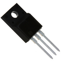
MOSFET N-CH 600V 4A TO-220FP
Manufacturer
ON Semiconductor
Datasheet
1.NDF04N60ZG.pdf
(9 pages)
Specifications of NDF04N60ZG
Fet Type
MOSFET N-Channel, Metal Oxide
Fet Feature
Standard
Rds On (max) @ Id, Vgs
2 Ohm @ 2A, 10V
Drain To Source Voltage (vdss)
600V
Current - Continuous Drain (id) @ 25° C
4.4A
Vgs(th) (max) @ Id
4.5V @ 50µA
Gate Charge (qg) @ Vgs
19nC @ 10V
Input Capacitance (ciss) @ Vds
535pF @ 25V
Power - Max
28W
Mounting Type
Through Hole
Package / Case
TO-220-3 Full Pack (Straight Leads)
Transistor Polarity
N-Channel
Resistance Drain-source Rds (on)
1.8 Ohms
Gate Charge Qg
19 nC
Forward Transconductance Gfs (max / Min)
3.3 S
Drain-source Breakdown Voltage
600 V
Continuous Drain Current
4.4 A
Power Dissipation
28 W
Maximum Operating Temperature
+ 150 C
Mounting Style
Through Hole
Minimum Operating Temperature
- 55 C
Lead Free Status / RoHS Status
Lead free / RoHS Compliant
Available stocks
Company
Part Number
Manufacturer
Quantity
Price


H
Q
Z
A
K
F
L
V
Q
G
H
1 2 3
4
1 2 3
B
−B−
N
D
0.25 (0.010)
3 PL
D
G
N
L
A
K
−Y−
F
M
B
PACKAGE DIMENSIONS
M
T
U
Y
TO−220 FULLPAK
http://onsemi.com
CASE 221D−03
CASE 221A−09
U
R
J
S
TO−220AB
ISSUE AE
ISSUE J
C
C
−T−
7
J
−T−
S
R
SEATING
PLANE
SEATING
PLANE
NOTES:
NOTES:
1. DIMENSIONING AND TOLERANCING PER ANSI
2. CONTROLLING DIMENSION: INCH.
3. DIMENSION Z DEFINES A ZONE WHERE ALL
1. DIMENSIONING AND TOLERANCING PER ANSI
2. CONTROLLING DIMENSION: INCH
3. 221D-01 THRU 221D-02 OBSOLETE, NEW
STYLE 5:
Y14.5M, 1982.
BODY AND LEAD IRREGULARITIES ARE
ALLOWED.
Y14.5M, 1982.
STANDARD 221D-03.
STYLE 1:
DIM
A
B
C
D
F
G
H
K
L
N
Q
R
S
T
U
V
Z
J
DIM
PIN 1. GATE
G
Q
A
B
C
D
F
H
J
K
L
N
R
S
U
PIN 1. GATE
2. DRAIN
3. SOURCE
4. DRAIN
0.570
0.380
0.160
0.025
0.142
0.095
0.110
0.014
0.500
0.045
0.190
0.100
0.080
0.045
0.235
0.000
0.045
2. DRAIN
3. SOURCE
MIN
0.617
0.392
0.177
0.024
0.018
0.503
0.048
0.122
0.099
0.092
0.239
0.116
0.118
---
MIN
0.100 BSC
0.200 BSC
INCHES
INCHES
0.620
0.405
0.190
0.035
0.161
0.105
0.155
0.025
0.562
0.060
0.210
0.120
0.055
0.255
0.050
0.080
0.110
MAX
0.635
0.419
0.193
0.039
0.129
0.135
0.025
0.541
0.058
0.138
0.117
0.113
0.271
---
MAX
14.48
12.70
MILLIMETERS
MIN
9.66
4.07
0.64
3.61
2.42
2.80
0.36
1.15
4.83
2.54
2.04
1.15
5.97
0.00
1.15
15.67
12.78
---
MILLIMETERS
MIN
9.96
4.50
0.60
2.95
3.00
0.45
1.23
3.10
2.51
2.34
6.06
2.54 BSC
5.08 BSC
15.75
10.28
14.27
MAX
4.82
0.88
4.09
2.66
3.93
0.64
1.52
5.33
3.04
2.79
1.39
6.47
1.27
2.04
16.12
10.63
13.73
---
MAX
4.90
1.00
3.28
3.43
0.63
1.47
3.50
2.96
2.87
6.88
Related parts for NDF04N60ZG
Image
Part Number
Description
Manufacturer
Datasheet
Request
R

Part Number:
Description:
ON Semiconductor [VOLTAGE REGULATOR]
Manufacturer:
ON Semiconductor
Datasheet:
Part Number:
Description:
357-036-542-201 CARDEDGE 36POS DL .156 BLK LOPRO
Manufacturer:
ON Semiconductor
Datasheet:
Part Number:
Description:
357-036-542-201 CARDEDGE 36POS DL .156 BLK LOPRO
Manufacturer:
ON Semiconductor
Datasheet:
Part Number:
Description:
357-036-542-201 CARDEDGE 36POS DL .156 BLK LOPRO
Manufacturer:
ON Semiconductor
Datasheet:
Part Number:
Description:
357-036-542-201 CARDEDGE 36POS DL .156 BLK LOPRO
Manufacturer:
ON Semiconductor
Datasheet:
Part Number:
Description:
357-036-542-201 CARDEDGE 36POS DL .156 BLK LOPRO
Manufacturer:
ON Semiconductor
Datasheet:
Part Number:
Description:
357-036-542-201 CARDEDGE 36POS DL .156 BLK LOPRO
Manufacturer:
ON Semiconductor
Datasheet:
Part Number:
Description:
357-036-542-201 CARDEDGE 36POS DL .156 BLK LOPRO
Manufacturer:
ON Semiconductor
Datasheet:
Part Number:
Description:
357-036-542-201 CARDEDGE 36POS DL .156 BLK LOPRO
Manufacturer:
ON Semiconductor
Datasheet:
Part Number:
Description:
357-036-542-201 CARDEDGE 36POS DL .156 BLK LOPRO
Manufacturer:
ON Semiconductor
Datasheet:
Part Number:
Description:
357-036-542-201 CARDEDGE 36POS DL .156 BLK LOPRO
Manufacturer:
ON Semiconductor
Datasheet:
Part Number:
Description:
Manufacturer:
ON Semiconductor
Datasheet:
Part Number:
Description:
Manufacturer:
ON Semiconductor
Datasheet:
Part Number:
Description:
Manufacturer:
ON Semiconductor
Datasheet: